N
ew Jersey Stormwater Best Management Practices Manual March 2024
Chapter 12: Soil Testing Criteria Page 1
12. SOIL TESTING CRITERIA
Introduction
Understanding the character and saturated hydraulic conductivity of surface and subsurface soils at a
proposed land development site is crucial to the design of stormwater best management practices (BMPs)
that meet the requirements of the New Jersey Stormwater Management rules at N.J.A.C. 7:8 (the Rules).
In particular, how a soil responds to rainfall, measured by its ability to absorb and infiltrate some of that
rainfall, is a required input parameter when computing both pre- and post-development runoff and
recharge rates. Similarly, soil saturated hydraulic conductivity is a critical parameter in the design of
stormwater BMPs that rely upon infiltration.
The term “permeability,” which is used throughout this chapter, has the meaning specified below.
a quantitative description of the ability of a saturated soil to transmit water vertically
downward through a soil horizon or substratum. The soil permeability in vertical direction is
assumed to be the vertical saturated hydraulic conductivity when the hydraulic gradient is
equal to one.
W
hen Soil Testing is Needed:
Below are five major ways soil testing is relevant to the design of stormwater management BMPs to meet
the stormwater runoff water quality, stormwater runoff water quantity and groundwater recharge
requirements:
1. Determining Hydrologic Soil Group (HSG) for calculating stormwater runoff,
2. Determining the soil series for groundwater recharge calculations,
3. Determining the Seasonal High Water Table (SHWT) to meet the BMP design separation standard,
4. Determining the soil hydraulic conductivity for BMP design and as-built testing and
5. Determining the input parameters for a groundwater mounding analysis.
The chapter is therefore divided into five sections in order to provide guidance on proper testing and the
default values that must be used when testing is not performed. Each section begins on the page number
listed in the table on the following page.

New Jersey Stormwater Best Management Practices Manual March 2024
Chapter 12: Soil Testing Criteria Page 2
Section
No.
Contents
Page
No.
1 Methods for Identifying HSGs and Soil Series: 3
1a HSG and Soil Series Designations from the NRCS Soil Survey 4
1b
Default HSG and Soil Series Designations for Runoff Computations
and the NJGRS Spreadsheet
5
1c Hydrologic Soil Group Testing Procedures 7
1d Seasonal High Water Table Location 11
1e Perched Water Table Requirements 13
2 Soil Tests for Stormwater Management BMPs: 14
2a Soil Testing Requirements for Infiltration BMPs 15
2b
Soil Testing Requirements for Non-Infiltration BMPs with a
required separation from the SHWT
22
2c Soil Log Requirements 22
3 Soil Hydraulic Conductivity Testing: 27
3a Acceptable Soil Hydraulic Conductivity Test Methods 27
3b
Hydraulic Conductivity Testing in Fractured Bedrock
27
4
Construction and Post-Construction Oversight and
Soil Hydraulic Conductivity Testing:
28
4a Construction and Post-Construction Oversight Requirements 28
4b Post-construction Hydraulic Conductivity Testing 28
5
Determination of the Input Parameters for Groundwater
Mounding Analyses
29

New Jersey Stormwater Best Management Practices Manual March 2024
Chapter 12: Soil Testing Criteria Page 3
In addition, the chapter includes an Addendum on the testing procedures listed in the table below:
Part
Addendum Contents
Page
No.
A1 Percolation Test 32
A2 Tube Permeameter Test 37
A3 Basin Flooding Test 44
A4 Modified Basin Flooding Test 45
A5 Single Ring Infiltration Test 47
General Notice
It is the responsibility of the company or persons performing or witnessing subsurface investigations and
soil hydraulic conductivity tests to comply with all applicable Federal, State and local laws and regulations
governing occupational safety, including, but not limited to, the requirements such as N.J.A.C. 7:9A-
5.2(e)3 and Occupation Safety and Health Administration 1926, Subpart P. All soil profile pits, soil borings
and soil hydraulic conductivity tests, along with any associated documentation, shall be conducted under
the direct supervision of a licensed New Jersey professional engineer. During all subsurface investigations
and soil test procedures, adequate measures shall be taken to ensure personnel safety and prohibit
unauthorized access to the excavations at all times. Entering a soil pit excavated below the water table
can be extremely dangerous and should be avoided unless the pit is relatively shallow and the sides of the
pit have been stepped and sloped to eliminate the likelihood of sudden and severe cave-in of the pit.
Section 1: Methods for Identifying HSGs and Soil Series
For drainage area runoff computations using the Natural Resources Conservation Service (NRCS)
methodology, knowledge of the Hydrologic Soil Group (HSG) to which the soil, or soils, present on a site
belongs is required, particularly for soils with pervious land cover. HSG is a measure of the runoff potential
of the surface soil layer. NRCS classifies soils into four HSGs, which are arranged alphabetically, i.e., ‘A’
through ‘D,’ in order from least to most likely to generate stormwater runoff. The soil series and HSG
impact the computations to establish the groundwater recharge and runoff conditions necessary to
evaluate compliance with the recharge and quantity control criteria of the Stormwater Management Rules.
In accordance with NRCS recommendations, HSG is typically determined through information
available from the NRCS Web Soil Survey, which, as its name indicates, is available on the internet.
The NRCS Web Soil Survey is used to establish the existing soils condition and the associated HSG for
the soil series.
However, at certain locations, an HSG determination is not available, either because the site contains
fill or sufficient information was not available to determine the HSG present. These lands may be
labeled with a soil series designation of Urban Land, Cut and Fill Land or Made Land, among others,
N
ew Jersey Stormwater Best Management Practices Manual March 2024
Chapter 12: Soil Testing Criteria Page 4
and have no HSG designation and/or are accompanied with a qualifying statement such as, “The
properties and characteristics of these soils differ greatly from place to place. Onsite investigation
and evaluation are needed for most uses.”
For other locations, direct soil observations and tests may indicate that a soil has an HSG classification
that is different than the one provided by the NRCS Web Soil Survey.
As a result, a methodology is needed to associate these areas, or other indeterminately and previously
altered areas in the State, with an applicable soil series and HSG, as well as for instances where map
classifications do not represent field conditions.
Subsection 1a: HSG and Soil Series Designations from the NRCS Soil Survey
The NRCS Web Soil Survey provides soil information online as an interactive web page:
https://websoilsurvey.nrcs.usda.gov/app/, for which the user’s guide is found online at:
https://websoilsurvey.nrcs.usda.gov/app/Help/WSS_HomePage_HowTo.pdf.
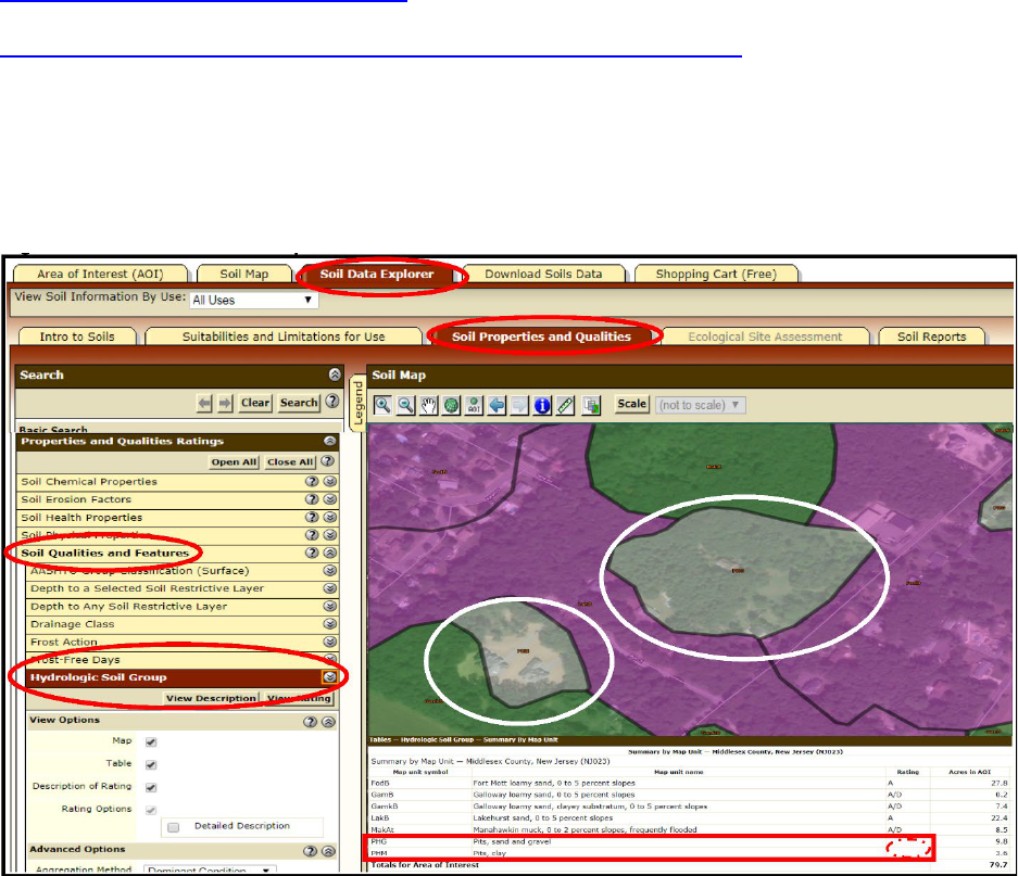
On the main page of the NRCS Web Soil Survey site, click on the circular shape labeled “Start WSS.” The
HSG and soil series designations are found under the tab “Soil Data Explorer” and subtab “Soil Properties
and Qualities,” and under the drop-down menu “Soil Qualities and Features,” followed by “Hydrologic Soil
Group” shown in Figure 12-1a, each of which are circled in red in the image below.
Figure 12-1a: NRCS Web Soil Survey
New J
ersey Stormwater Best Management Practices Manual March 2024
Chapter 12: Soil Testing Criteria Page 5
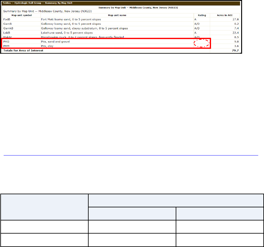
A close up of the lower right legend is provided in Figure 12-1b below. The column titled “Map unit name”
contains the information on the soil series and the soil types for each soil unit depicted as a shape on the
map in Figure 12-1a. HSG information is shown under column titled “Rating”. The two areas highlighted
in gray, within the white ovals, are those map units identified by the red rectangle for which HSG and soil
series have not been determined. The soils in the undetermined HSG and soil series may be determined
by the methods in Subsections 1b and 1c, which are discussed on Pages 5 and 7, respectively. Information
on dual-rated soils shown above and on the following page, i.e., those with a rating of ‘A/D,’ is provided
on Page 7.
Figure 12-1b: NRCS Web Soil Survey Summary by Map Unit Legend
Subsection 1b: Default HSG and Soil Series Designations
Where HSG information from the NRCS Web Soil Survey or a published survey is either unavailable or
inconsistent with conditions in the field, the runoff computations for pre- and post-developed drainage
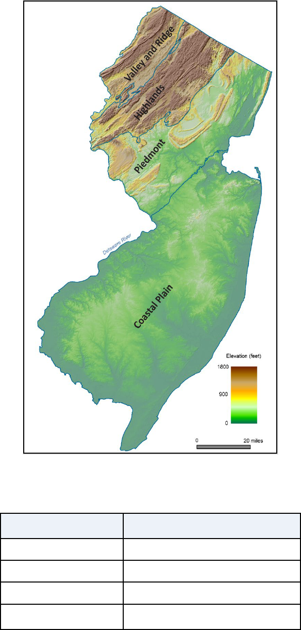
area conditions may be based upon default HSGs. These default HSGs are shown in Table 12-1 below for
drainage areas within and outside New Jersey’s coastal plain, which is depicted in the graphic provided as
Figure 12-2 on the next page. Additionally, the NJDEP Bureau of GIS website allows the user to locate an
address to obtain information regarding the physiographic province in which a project is located. Use the
link provided below:
https://gisdata-njdep.opendata.arcgis.com/datasets/20377d0dc1fe41f1ab2d9d0897844441_20/explore.
If the designer engineer does not wish to utilize these assumed hydrologic soil groups, a process is outlined
in the remainder of this chapter to establish the HSG based on a site-specific investigation.
Table 12-1: Default Hydrologic Soil Group for Runoff Computations
Site Condition
Site Location (see Figure 12-2)
In Coastal Plain
Outside Coastal Plain
Pre-construction HSG A HSG B
Post-construction HSG D HSG D
Once the default HSG is selected, in accordance with the table above, the default soil series shown in
Table 12-2 may be used in the NJGRS for groundwater recharge calculations.
N
ew Jersey Stormwater Best Management Practices Manual March 2024
Chapter 12: Soil Testing Criteria Page 6
Figure 12-2: Physiographic Provinces of NJ
Image modified from the New Jersey Geological Survey Information Circular,
“Physiographic Provinces of New Jersey, 2006” and used with permission.
Table 12-2: Default Soil Series for NJGRS Recharge Computation
HSG
Soil Series Name
A Fort Mott
B Nixon
C Readington
D
Any soil series that results in
zero annual recharge
Carteret
+
Trenton
+
+
+
Monmouth
Junction
Princeton
Junction

N
ew Jersey Stormwater Best Management Practices Manual March 2024
Chapter 12: Soil Testing Criteria Page 7
Subsection 1c: Hydrologic Soil Group Testing Procedures
Location and Number of Required Soil Explorations
If the HSG designation is either undetermined from the NRCS Web Soil Survey, dual-rated on the Web Soil
Survey or inaccurate with respect to field conditions, then field observations and soil testing must be
performed. The classification of HSG is in accordance with the NRCS National Engineering Handbook, Part
630 – Hydrology (NEH), Chapter 7 Hydrologic Soil Groups, January 2009, available at:
https://directives.sc.egov.usda.gov/22526.wba.
From Page 7-1 of the above-referenced document, the assignment of HSG “is determined by the water
transmitting soil layer with the lowest saturated hydraulic conductivity and depth to any layer that is more
or less water impermeable (such as a fragipan or duripan) or depth to a water table (if present). The least
transmissive layer can be any soil horizon that transmits water at a slower rate relative to those horizons
above or below it.” Table 7-1 of NEH Chapter 7 lists the criteria for assignment of HSG.
In order to obtain the information needed for determining the appropriate HSG designation, one or more
soil profile pits are needed to collect detailed information on groundwater conditions and soil morphology.
Data recorded from one or more soil borings must then be compared to the reference soil profile pit to
confirm consistency between the profile pit and the soil boring. Where soil and/or groundwater
properties vary significantly between soil boring and profile pit explorations, additional soil profile pits
must be conducted, as necessary, to resolve such differences and accurately characterize the soil(s)
present in the mapping unit.
Note that there are dual HSG classes ‘A/D’, ‘B/D’ and ‘C/D’ in Table 7-1 of NEH. The dual class designation
means that a soil can be classified as the ‘A,’ ‘B’ or ‘C’ soil appearing to the left of the slash, but since this
soil group often has the SHWT within 24 inches of the ground surface, investigation is needed. If the
SHWT is determined to be within 24 inches of the ground surface, the soil must be classified as HSG ‘D’
soil. For example, a sandy soil that has a hydraulic conductivity of 10 in/hr, for which the SHWT is
determined to be 22 inches below the ground surface would be classified as HSG ‘D’ despite its high
hydraulic conductivity.
Soil Boring and Profile Pit Locations and Allowable Substitutions
In all instances, a soil profile pit may be conducted in place of a required soil boring; however, a soil boring
cannot be used as a substitute for a soil profile pit except as follows:
Two soil borings may be conducted in the place of a required soil profile pit with a soil profile pit located
at the closest available location representative of the soil boring locations under the following three
circumstances:
1. In areas where a soil profile pit would substantially disturb the existing area and create an
undesirable condition
,
2. Where significant environmental disturbance will occur in an area that is not intended for future
development o
r
New Jersey Stormwater Best Management Practices Manual March 2024
Chapter 12: Soil Testing Criteria Page 8
3. Where the excavation of soil profile pits will be still unsafe after observing all excavation safety
guidance, protocols and requirements established or provided by any of the entities listed below:
A Federal entity - such as the Occupational Safety and Health Administration,
A State agency, bureau or other regulatory authority or
Any local governmental entity.
The following standards and determinations apply:
Where soil and/or groundwater properties vary significantly between soil explorations, additional soil
profile pits shall be conducted as necessary to resolve such differences and accurately characterize
the subsurface conditions.
All soil explorations shall be located generally equidistant from each other and the boundaries of the
mapping unit to maximize the ability to interpolate between test locations so as to provide adequate
characterization of the mapping unit’s soil.
If the location of the soil profile pit is not representative of the soil borings taken, it is the responsibility
of the design engineer to demonstrate the consistency of soil profile pit data to the soil characteristics
at the location of the soil borings.
Number of Soil Explorations Required
The size of the soil mapping unit for which the HSG is either unknown or inaccurate determines the
minimum number and types of soil explorations required. Examples of the number of required soil profile
pits and soil borings are in Table 12-3 located on the next page.
a. Soil Mapping Unit < 0.5 ac: Where the HSG is unknown for a mapping unit of less than one half
acre, as shown on the NRCS Web Soil Survey, a minimum of one soil profile pit and one soil boring
shall be conducted within that mapping unit.
b. Soil Mapping Unit ≥ 0.5 ac and ≤ 2 ac: On those areas of the development parcel for which the
HSG is either unknown or inaccurate with respect to field conditions, for a mapping unit greater
than or equal to one half acre and less than or equal to two acres, as shown on the NRCS Web Soil
Survey, a minimum of one soil profile pit and four soil borings shall be conducted within each soil
mapping unit.
c. Soil Mapping Unit > 2 ac: Where the HSG is unknown for a mapping unit larger than two acres
within the limits of the overall site, in addition to the required numbers in b., a minimum of one
additional soil profile pit and two additional soil borings shall be conducted for each additional
two acres.

New Jersey Stormwater Best Management Practices Manual March 2024
Chapter 12: Soil Testing Criteria Page 9
Table 12-3: Example 1 - Soil Explorations vs. Map Unit Size
Map Unit Size
Number of Soil Profile Pits
Number of Soil Borings
0.45 ac 1 1
1.9 ac 1 4
2.6 ac 1 + 1 = 2 4 + 2 = 6
Depth of Soil Profile Pits and Boring:
The determination of the soil HSG is based upon the depth to restrictions (i.e., the depth to the SHWT and
soil morphological characteristics which restrict the vertical movement of water including, but not limited
to, abrupt textural boundaries, fragipans, dense materials, bedrock and ortstein horizons and the
hydraulic conductivity of the most restrictive soil horizon above either the restriction or the SHWT. The
presence and depth of these restrictions must be included in the soil log of both the soil profile pits and
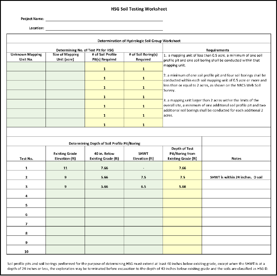
the soil borings. Soil profile pits and soil borings performed for the purpose of determining HSG must
extend at least 40 inches below existing grade, except when the SHWT is at a depth of 24 inches or less,
the exploration may be terminated before excavation to the depth of 40 inches below existing grade and
the soils are classified as HSG D. If the same soil profile pit or soil boring will also be used for the test of
soil hydraulic conductivity, the depth of the exploration shall follow the requirements set forth in
Subsection 2a on Page 15. Examples of the required depth for HSG soil exploration are in Table 12-4
below.
Table 12-4: Example 2 – HSG Soil Exploration Required Depth Determinations
Elevation
Example 2-A
Example 2-B
Example 2-C
Ex. Grade (EG) = EL. 11 EL. 9 EL. 9
40 in. Below EG= EL. 7.66 EL. 5.66 EL. 5.66
SHWT =
SHWT was not
encountered
EL. 7.5
EL. 6.5
Required
Elevation of Soil
Pit or Boring
Excavation =
Answer: EL. 7.66
SHWT was not within
24 inches below the
existing grade. The
depth is required
down to at least 40
inches below the
existing grade.
Answer: EL. 7.5
SHWT was within 24
inches below the
existing grade. The soil
is designated as HSG D
soil. The excavation
may be terminated
before to the depth of
40 inches below the
existing grade.
Answer: EL. 5.66
SHWT was not within
24 inches below the
existing grade. The
depth is required down
to at least 40 inches
below the existing
grade.
Note: “Ex.” Denotes Existing and “EL.” Denotes Elevation

New Jersey Stormwater Best Management Practices Manual March 2024
Chapter 12: Soil Testing Criteria Page 10
Soil Series for NJGRS Recharge Computation
For the soil series determinations in the New Jersey Groundwater Recharge Spreadsheet (NJGRS), the user
may input the default soil series name matching the HSG designation. Alternatively, the user may identify
the soil series by the taxonomic class and soil series description. The first step is to identify the soil
taxonomic class by using the NRCS publication, titled:
A Basic System of Soil Classification for Making and Interpreting Soil Surveys. 2nd edition. Natural
Resources Conservation Service. 1999. U.S. Department of Agriculture Handbook 436, available
online at:
https://nrcspad.sc.egov.usda.gov/DistributionCenter/product.aspx?ProductID=703
The second step is to look up the soil series name that matches the soil classification described in the
taxonomic class. The Soil and Plant Science Division maintains the official soil series descriptions in a file-
share storage system, which is available online at:
https://www.nrcs.usda.gov/conservation-basics/natural-resource-concerns/soils/official-series-descriptions-tools
and the soil series classifications is in a database, which is available online at:
https://www.nrcs.usda.gov/resources/data-and-reports/soil-series-classification-database-sc
For more details, see the National Soil Survey Handbook, Natural Resources Conservation Service, U.S.
Department of Agriculture online at:
https://www.nrcs.usda.gov/resources/guides-and-instructions/national-soil-survey-handbook
On the following page is an example of an Excel spreadsheet that may be used to calculate the number
of soil profile pits and borings required for the determination of an HSG designation. The spreadsheet
may be downloaded as part of an Excel workbook from the Department website, under the heading for
Chapter 12 of the BMP Manual, at:
https://dep.nj.gov/stormwater/bmp-manual/
New Jersey Stormwater Best Management Practices Manual March 2024
Chapter 12: Soil Testing Criteria Page 11
Figure 12-3: Example of an HSG Soil Testing Worksheet
Subsection 1d: Seasonal High Water Table (SHWT) Location
This subsection establishes the guidelines to be followed for determining the upper limit of the zone of
saturation, which is known as the Seasonal High Water Table (SHWT). As mentioned earlier, the location
of the SHWT can be very important to determining the HSGs present on a site. Additionally, most of the
stormwater management BMPs presented in this manual must meet the minimum separation from the
SHWT specified in the relevant subchapter. The location of the SHWT shall be determined by one of the
following methods:

New Jersey Stormwater Best Management Practices Manual March 2024
Chapter 12: Soil Testing Criteria Page 12
1. Where mottling showing redoximorphic features is observed at any season of the year, the SHWT
shall be taken as the highest level at which the mottling is observed, except when the water table
is observed at a level higher than the level of the redoximorphic depletions or concentrations. For
details on determining whether saturated soils are present, the guidance document published by
NRCS, “Field Indicators of Hydric Soils in the United States” may be used.
2. Where mottling showing redoximorphic features is not observed, the SHWT shall be determined
based upon either of the following methods, depending on the time of the year during which the
testing is performed:
a. During the months of January through April, inclusive, water levels may be measured directly
within soil profile pits or borings. Whenever the Department determines that there has been
a significant departure from normal climatic conditions, the Department may, with due notice
to the administrative authority, lengthen or shorten the period allowed for direct
measurement during any given year. In low lying coastal areas where groundwater levels
fluctuate with the tides, measurements shall be taken at the time of highest groundwater
elevation in response to tidal fluctuation or
b. During other times of the year, the depth to the SHWT may be obtained from the NRCS Web
Soil Survey provided that the soil series present at the site is identified based upon
comparison of soil profile morphology observed within a soil profile pit and the soil profile
description provided for the soil series in question within the NRCS Web Soil Survey. In cases
where SHWT is shown as a range of elevations in the NRCS Web Soil Survey, the highest
elevation of the range shall be used as the SHWT.
Below, and on the following page, are Tables 12-5 and 12-6 providing guidance on SHWT determination,
depending on observations and the time of year. Table 12-5 corresponds with Item 1 within this
subsection, and Table 12-6 corresponds with Item 2.
Table 12-5: SHWT Determination - Mottling Shows Redoximorphic Features within Soil Exploration
Time
Period
Observation
Conclusion
January-
December
Water table is observed above
mottling
showing redoximorphic
features
SHWT is at location of observed water table
Water table is observed below
mottling
showing redoximorphic
features or
no water table is
observed
within the soil
exploration depth
SHWT is at location of mottling showing
redoximorphic features
New Jersey Stormwater Best Management Practices Manual March 2024
Chapter 12: Soil Testing Criteria Page 13
Table 12-6: SHWT Determination - Mottling Shows No Redoximorphic Features within Soil Exploration
Time
Period
Observation
Conclusion
January-
April
Water table is observed SHWT is at location of the observed water table
Water table is not observed
SHWT is assumed to be at the lowest elevation of
soil exploration
May-
December
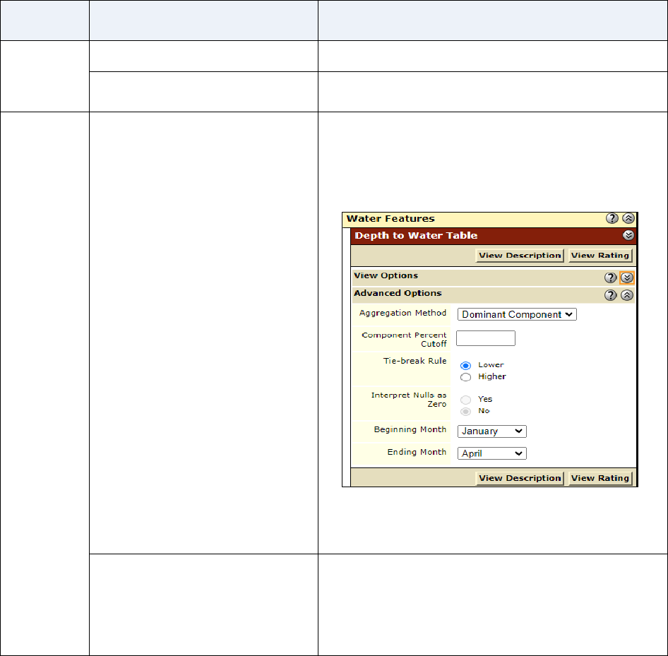
The soil profile observed in a
profile pit is verified against the
detailed information provided in
the NRCS Web Soil Survey
The depth to water table given in NRCS Web Soil
Survey may be used as the SHWT, provided that the
Beginning Month and the Ending Month is between
January and April in the Advanced Options for Depth
to Water Table:
Note: If a range is provided for the water table
elevation, the highest elevation of the range
shall be used as the SHWT.
The soil profile in a profile pit is
not verified against the detailed
information provided in the NRCS
Web Soil Survey
The SHWT is undetermined. Soil test following
Subsection 1d needs to be conducted in January
through April or alternatively conducted during May
through December at other locations in compliance
with Section 2.
Subsection 1e: Perched Water Table Requirements
If a groundwater table is encountered during soil exploration, in accordance with N.J.A.C. 7:9-5.8 (e), it
shall be considered to be perched if it is present immediately above a hydraulically restrictive horizon,
such as clay or fragipan, underlain by a layer of permeable unsaturated soil which is free of mottling and
has a chroma of four or higher. In cases where a perched water table exists at the location of a BMP,
additional soil testing is required to determine the extent of the hydraulically restrictive horizon within
the area of the BMP, which is sometimes referred to as the “footprint.” The following requirements must
be followed:
New Jersey Stormwater Best Management Practices Manual March 2024
Chapter 12: Soil Testing Criteria Page 14
Soil profile pits, separated by equal distances, must be conducted along the boundary of the footprint.
The number of soil profile pits conducted must be sufficient to determine the extent of the
hydraulically restrictive horizon in all directions.
A hydraulic head test, as defined at N.J.A.C. 7:9A-5.9, shall be conducted in the soil that immediately
underlies a perched water table to determine whether an artesian condition exists. An artesian
condition is defined at N.J.A.C. 7:9A-5.8 (f).
If the hydraulically restrictive horizon extends beyond the footprint, the infiltration BMP must be
relocated to another location that is not affected by the perched water table or the highest elevation
of the perched water table shall be assumed to be the SHWT for all aspects of design and soil testing.
If the hydraulically restrictive horizon does not extend beyond the footprint, the hydraulically
restrictive horizon may be excavated and replaced with sand.
Under no circumstances may an infiltration BMP be located in soils that exhibit artesian
groundwater conditions. If artesian conditions exist, the hydraulically restrictive layer may not be
excavated and replaced. The proposed infiltration BMP must be relocated to avoid the artesian
aquifer.
Section 2: Soil Tests for Stormwater Management BMPs
For the purpose of determining the soil testing requirements of this chapter, stormwater BMPs may be
broken into two categories: infiltration BMPs and non-infiltration BMPs. Stormwater infiltration BMPs
are those BMPs which rely on infiltration for groundwater recharge, stormwater runoff quality and/or
stormwater runoff quantity control. Infiltration BMPs include, but are not limited to, a bioretention
system without an underdrain, a dry well, an infiltration basin, a sand filter without an underdrain, a
pervious paving system without an underdrain or a GI MTD that infiltrates the runoff into subsoil. Non-
infiltration stormwater BMPs are BMPs which do not utilize infiltration to meet any of the design and
performance standards for stormwater management measures.
Saturated soil hydraulic conductivity and depth to SHWT are of high importance for the design of
stormwater BMPs. Infiltration BMPs are required to test the saturated soil hydraulic conductivity and
identify the depth to SHWT at the proposed BMP location. Certain non-infiltration BMPs may require
knowledge of the SHWT but not the saturated soil hydraulic conductivity, such as an underdrained
bioretention basin, an underdrained sand filter, an underdrained pervious paving system, an extended
detention basin, subsurface gravel wetlands or a grass swale. Non-infiltration BMPs that require a
minimum separation from the SHWT are required to identify the depth to SHWT at the proposed BMP
location. Manufactured Treatment Devices that are not required to maintain a minimum separation to
SHWT, green roofs, blue roofs, above-grade cisterns and above-grade small-scale bioretention BMPs
situated on impervious structures, such as downspout planter boxes and vegetative filter strips are not
required to test the depth to the SHWT. Tables 5-1, 5-2 and 5-3 in the Stormwater Management rules
and Chapters 9, 10 and 11 of the BMP Manual list the minimum separation from the SHWT for stormwater
BMPs.
Take note: There are non-infiltration BMPs which do not require information on the SHWT, but these
may still require information on the saturated soil hydraulic conductivity to determine if the soil

New Jersey Stormwater Best Management Practices Manual March 2024
Chapter 12: Soil Testing Criteria Page 15
underneath and surrounding the basin is sufficiently impermeable to prevent excessive seepage, such as
standard constructed wetlands and wet ponds. Under such circumstances, the depth and location of the
soil exploration may not be limited to the requirements under this subsection. The design engineer needs
to conduct soil tests for the saturated soil hydraulic conductivity using their professional judgement and
the engineering needs.
Subsection 2a: Soil Testing Requirements for Infiltration BMPs
Required Quantity and Placement of Soil Explorations
For infiltration BMPs, soil profile pits and soil borings must be conducted in the infiltration area, which is
the area of the BMP providing infiltration. The infiltration area does not include the slope, side or wall
areas of a BMP. The location and numbers of soil profile pits and soil borings must meet the requirements
listed in Items 1 through 7 in the index below and covered on the subsequent pages. Example 3, found in
Table 12-7 on Page 18 illustrates the various requirements.
No.
Testing Requirement Applicability
Page
No.
1 Requirements for any infiltration BMP 15
2
Requirements for a site with one or more infiltration BMPs, each equal to
or less than five hundred square feet in area
16
3
Requirements for a site with one or more small-scale green infrastructure
BMPs that infiltrate runoff into subsoil, where each green infrastructure
BMP is greater than 500 square feet in area, exclusive of porous paving
systems
16
4 Requirements for a linear BMP 16
5 Allowable substitutions 17
6 Proximity of soil exploration(s) to the actual location of a BMP 17
7 When additional soil profile pit(s) may be required 18
1. Requirements for any infiltration BMP:
Except as specified in Items 2, 3 and 4 listed below, a minimum of two soil profile pits must
be excavated within the infiltration area of any proposed infiltration BMP to determine the
suitability and distribution of soil types and seasonal high water table present at location of
the BMP.
Placement of the test pits must be sufficient to provide adequate characterization of the
infiltration area.
For BMP infiltration areas larger than ten thousand square feet, a minimum of one additional
soil profile pit shall be conducted for each additional area of ten thousand square feet.
At least one test to establish the soil hydraulic conductivity must be conducted for each soil
profile pit.
New Jersey Stormwater Best Management Practices Manual March 2024
Chapter 12: Soil Testing Criteria Page 16
2. Requirements for a site with one or multiple infiltration BMPs including small-scale green
infrastructure BMPs, each equal to or less than five hundred square feet in area:
For sites with multiple infiltration BMPs, each with infiltration areas equal to or less than five
hundred square feet, a minimum of one soil profile pit per soil mapping unit where the
multiple BMPs will be located is required for the site. If the multiple infiltration BMPs are to
be located in different soil mapping units, each soil mapping unit must have one soil profile
pit. The location of the soil profile pit shall be at or near to the geographic center of all soil
borings of the infiltration BMPs within the same soil mapping unit.
One soil boring is required for each infiltration BMP.
For multiple BMPs located linearly along a roadway, in addition to the soil boring required in
each, one additional soil profile pit is required for every 2,000 linear feet.
The total number of required soil profile pits shall be placed generally equidistant from each
other so as to provide adequate characterization of the infiltration area.
At least one test to establish the soil hydraulic conductivity must be conducted for each soil
profile pit and soil boring.
3. Requirements for a site with one or more small-scale green infrastructure BMPs that infiltrate
runoff into subsoil, where each green infrastructure BMP is greater than 500 square feet in area,
excluding porous paving systems:
A soil profile pit is required for each soil mapping unit where a green infrastructure BMP is to
be located. The location of the soil profile pit shall be at or near to the geographical center of
all of the soil borings within the same soil mapping unit for a given green infrastructure BMP.
Two soil borings are required for each green infrastructure BMP.
For multiple green infrastructure BMPs located linearly along a roadway, in addition to the
soil borings in each green infrastructure BMP, one additional soil profile pit is required for
every 2,000 linear feet.
The total number of required soil profile pits shall be placed generally equidistant from each
other so as to provide adequate characterization of the infiltration area.
At least one test to establish the soil hydraulic conductivity must be conducted for each soil
profile pit and soil boring.
4. Requirements for a linear BMP:
A linear BMP is defined as a BMP with all of the following characteristics:
□ The length of the infiltration area is at least four times the width of the infiltration area,
i.e., the minimum length to width ratio is equal to or greater than 4:1,
□ The maximum width of the bottom of the linear BMP is twenty-five feet and
□ The maximum width of the top of the linear BMP is forty feet.
New Jersey Stormwater Best Management Practices Manual March 2024
Chapter 12: Soil Testing Criteria Page 17
A minimum of one soil profile pit must be conducted within each soil mapping unit. In each
soil mapping unit, the soil profile pit must be conducted within the first 500 linear feet of a
linear BMP.
Where the length of a linear BMP exceeds 500 linear feet, one additional soil profile pit must
be conducted for every 2,000 linear feet and one soil boring must be conducted at every 500-
foot interval.
The total number of required soil explorations shall be placed generally equidistant from each
other so as to provide adequate characterization of the infiltration area.
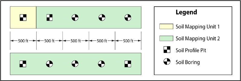
See Figure 12-4 below for a graphical representation of the required placement discussed above
for a linear BMP. Take note that soil profile pits from different soil mapping units may be more
distant from each other in order to obtain more information about the geomorphology
characteristics of the project.
Figure 12-4: Soil Exploration Locations for Linear Infiltration BMPs
5. Allowable substitutions
A soil profile pit may be substituted by soil borings only when the conditions stated in the
subsection titled
“Soil Boring and Profile Pit Locations and Allowable Substitutions,” which begins
on Page 7, are fully met.
6. Proximity of soil exploration(s) to the actual location of a BMP
The final location of a proposed BMP can differ from the location of a soil exploration. As long as
the proposed BMP is within the same soil mapping unit, a new soil exploration is not required
under the following circumstances:
If the soil explorations that have been performed are still within the infiltration area of the
BMP at its new location or
If the new location of the BMP is within 25 feet, in any direction, of all of the original soil
exploration location(s).

New Jersey Stormwater Best Management Practices Manual March 2024
Chapter 12: Soil Testing Criteria Page 18
7. When additional soil profile pit(s) may be required
Where soil and/or groundwater properties vary significantly between soil explorations,
additional soil profile pits shall be conducted as necessary to resolve such differences and
accurately characterize the subsurface conditions below the infiltration BMP.
See Example 3, in Table 12-7 below, to determine the number of soil profile pits and soil
borings necessary for a variety of stormwater infiltration BMPs of many sizes.
Table 12-7: Example 3 – Required Number of Soil Profile Pits and Soil Borings
Type of
Soil
Exploration
and Number
Required:
Example BMPs
9,000 sf
Infiltration
Basin
25,450 sf
Infiltration
Basin
35,000 sf
Porous Paving
System
10
Rain
Gardens
Each =
400 sf
4
Small-
Scale
Infiltration
Basins,
Each =
1,500 sf
2,500 ft
Linear
Bioretention
Swale
Soil
Profile
Pit(s)
2
4 Total:
2 (1
st
10,000 sf) +
1 (2
nd
10,000 sf)
+
1
(add’l. 5,450 sf)
5 Total:
2 (1
st
10,000 sf) +
1 (2
nd
10,000 sf)
+
1 (3
rd
10,000 sf)
+
1 (add’l. 5,000 sf)
1
1
2 Total
:
1 (1
st
500 ft) +
1 (2,000
ft)
Soil
Boring(s)
None
Required
None
Required
None
Required
10 Total
:
1 per
each
GI
BMP
8
3 Total:
1 per each 500
ft of length
after the first
500 feet
New Jersey Stormwater Best Management Practices Manual March 2024
Chapter 12: Soil Testing Criteria Page 19
Depth of Soil Exploration
Soil profile pits and soil borings performed for the purpose of designing an infiltration BMP must extend
to either a minimum depth of eight feet below the lowest elevation of the basin bottom or to a depth
that is at least twice the maximum potential water depth generated by the largest design storm,
whichever is greater.
Example 4 – Calculate the required depth and bottom elevation of the soil exploration for an
infiltration basin
An infiltration basin is proposed at a location where the existing grade is at EL. 50 ft. The proposed
elevation of the top of the 6 inch deep sand layer comprising the basin bottom is 5 ft below the existing
grade. The infiltration basin is proposed to infiltrate the Water Quality Design Storm (WQDS), which
produces a maximum depth of stormwater runoff equal to 2 ft, measured above the sand layer.
In this example, the lowest elevation of the basin bottom is the lower physical limit of the sand layer,
which is at EL. 50 – 5 – 0.5 = EL. 44.5 ft. The maximum potential depth of runoff to be infiltrated was
stated above to be 2 ft. Twice this depth is 4 ft; however, this depth is less than the 8 ft minimum
depth requirement stated above. Therefore, the soil exploration for the soil profile pit and/or soil
boring must extend down to EL. 44.5 – 8 = EL. 36.5 ft.
Location for soil samples or in-situ tests of the soil hydraulic conductivity
Soil hydraulic conductivity tests must be conducted on the most hydraulically restrictive horizon or
substratum above the SHWT or nonfractured bedrock but located below the lowest elevation of a BMP
and above whichever of the following depths is greater:
eight feet below the lowest elevation of the BMP or
to a depth equal to twice the maximum potential water depth in the BMP measured from the lowest
elevation of the BMP.
Take note: The lowest elevation of a BMP is bottom of the excavation of the BMP. Where a BMP has
a sand or soil layer, the lowest elevation is the bottom of the sand or soil layer. If soil replacement is
proposed beyond the required layers in the BMP, the depth is measured from the elevation of the
bottom of the required sand or soil layer.
Stormwater infiltration BMPs must not be installed in soils that exhibit artesian groundwater conditions.
Stormwater infiltration BMPs relying on fractured bedrock for exfiltration must not be installed without a
minimum of 2 feet between the bottom of the infiltration basin and the bedrock. In such a situation, the
design engineer must demonstrate that appropriate testing methods, as discussed in Section 3, are
utilized to establish the hydraulic conductivity of the infiltration BMP. The number of permeability tests
performed shall be no less than the number of tests required for determining the permeability in the soil.
Table 12-8, located on the following page, provides a number of examples illustrating these requirements.

New Jersey Stormwater Best Management Practices Manual March 2024
Chapter 12: Soil Testing Criteria Page 20
Table 12-8: Example 5 – Required Depth for Locating the Most Hydraulically Restrictive Layer
Criteria
Example BMPs
Bioretention
Basin
Infiltration Basin
w/ 6 in
Sand Layer
w/ 6 in
Sand Layer
w/ 5 ft
Sand
Replacement
Below
Basin
Bottom*
w/ 10 ft
Sand
Replacement
Below
Basin
Bottom*
Maximum
Standing Water
Depth (ft)
1
2
2
2
2
SHWT (ft)
Below the
Basin Bottom
12
12
4**
12
18
Depth range to
locate the most
hydraulically
restrictive
layer(s)
0 to 8 ft
below the
bottom of
the basin
0 to 8 ft
below the
bottom of the
sand layer
0 to 4 ft
below the
bottom of the
sand layer
5 to 12 ft
below the
bottom of the
basin
10 to 18 ft
below the
bottom of the
basin
*The depth of sand replacement specified does not include the required 0.5 ft deep sand layer comprising the surface of the basin
infiltration area.
**The location of the SHWT is the limiting factor in this case
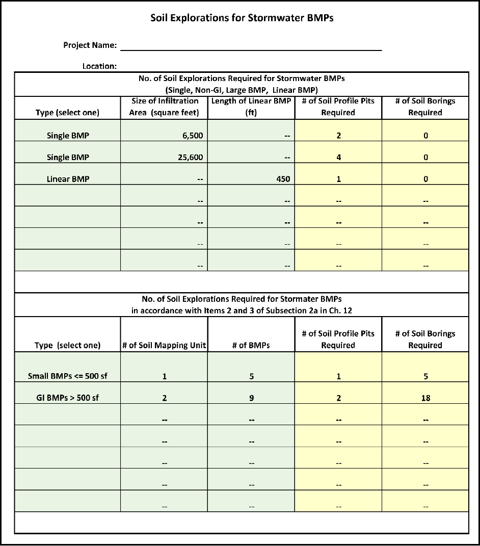
On the following page is an example of an Excel spreadsheet that may be used to calculate the number of
soil profile pits and borings, plus the depth(s), required for an infiltration BMP as part of soil hydraulic
conductivity testing. The workbook including this spreadsheet may be downloaded from the Department
website, under the heading for Chapter 12 of the BMP Manual, at:
https://dep.nj.gov/stormwater/bmp-manual/
New Jersey Stormwater Best Management Practices Manual March 2024
Chapter 12: Soil Testing Criteria Page 21
Figure 12-5a: Example of a Hydraulic Conductivity Testing Worksheet for Infiltration BMPs
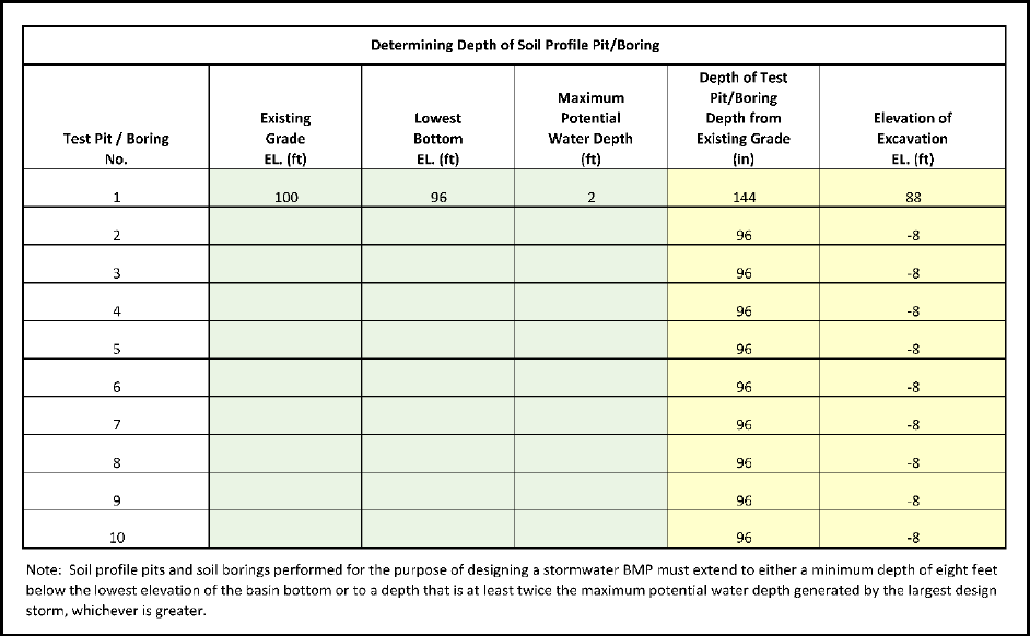
On the following page is depicted the portion of example Excel spreadsheet for determining the depth
of the soil profile pit/boring .
New Jersey Stormwater Best Management Practices Manual March 2024
Chapter 12: Soil Testing Criteria Page 22
Figure 12-5b: Hydraulic Conductivity Test Worksheet for Infiltration BMPs –
Determining the Depth of Soil Profit Pit/Boring
Subsection 2b: Soil Testing for Non-Infiltration BMPs with a Required Separation from
the SHWT
The location and depth of soil exploration in Subsection 2a may be followed with these clarifications:
The BMP area of a non-infiltration BMP in this Subsection 2b shall be used in place of the infiltration
area for an infiltration BMP stated in Subsection 2a.
The BMP area of a non-infiltration BMP refers to the bottom area of the BMP, not including the slope,
side or wall areas of a BMP. The soil explorations shall still be equidistant from each other within this
area.
Subsection 2c: Soil Log Requirements
A soil log must be prepared for each soil profile pit and soil boring. The soil boring log must be legible and,
at a minimum, provide all of the following:
the date of the soil exploration,
the map showing the location of the soil exploration,
the actual elevation of the existing ground surface at the location of the soil exploration,
New Jersey Stormwater Best Management Practices Manual March 2024
Chapter 12: Soil Testing Criteria Page 23
the elevation of the proposed grade and/or elevation of the lowest level in the bottom of the
proposed BMP,
the elevations of the saturated soil hydraulic conductivity test or sample location(s) (required only
when the test of saturated soil hydraulic conductivity is conducted),
the depth, or the elevation and thickness of each soil horizon and the depth to the substratum,
the dominant matrix or background and mottle colors using the Munsell system of classification for
hue, value and chroma,
the appropriate textural class as shown on the USDA textural triangle,
the volume percentage of coarse fragments larger than two (2) millimeters in diameter,
the abundance, size and contrast of mottles,
the soil water state, using standard USDA classification terminology,
the presence of any soil horizon, substratum or other feature that exhibits an in-place soil hydraulic
conductivity less than 1 inch per hour,
the depth and occurrence of soil restrictions including, but not limited to, abrupt textural boundaries
likely to restrict the movement of water, e.g., fragipans, dense materials, bedrock and ortstein
horizons,
the depth to the seasonally high ground water level, either perched or regional,
the static (stabilized) water level, presence of redoximorphic features,
any observed seepage or saturation and
natural soil drainage class(es).
In addition to all of the above, the soil profile pit log must also provide the soil structure and soil
consistence using standard USDA classification terminology.
The results and locations of all soil profile pits, borings and soil hydraulic conductivity tests, both passing
and failing, must be included in the Stormwater Management Report submitted to the appropriate review
agency.
A simple version of a sample soil log is depicted in Figure 12-6 on the next page.
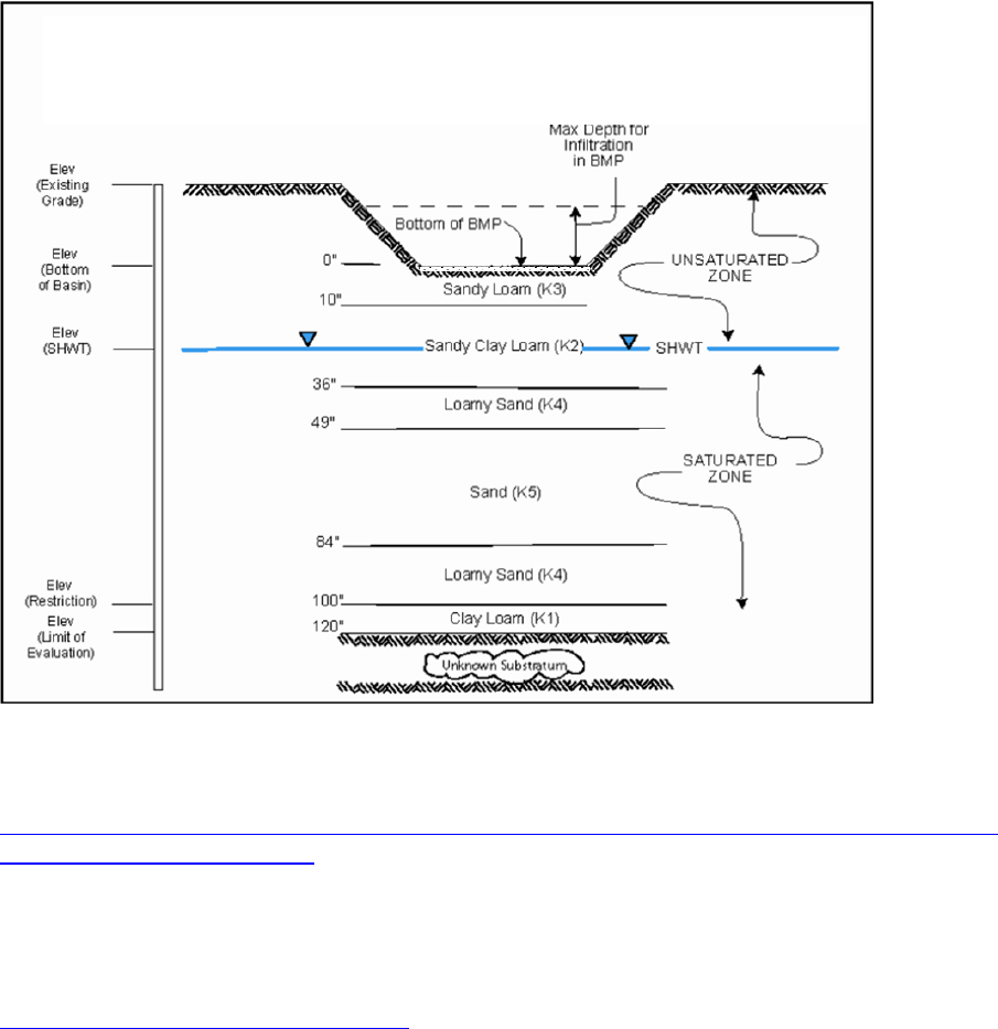
New Jersey Stormwater Best Management Practices Manual March 2024
Chapter 12: Soil Testing Criteria Page 24
Figure 12-6: Sample Soil Log (For Direct Observation of SHWT)
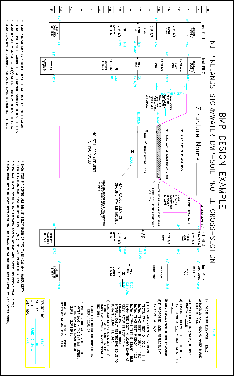
On Page 25, Figure 12-7 depicts a soil profile cross-section example obtained from the Pinelands
Commission, which is available online at:
https://www.state.nj.us/pinelands/appli/tools/new%20forms/Pinelands%20Stormwater%20BMP%20Cross%20
Section%20Design%20Example.pdf.
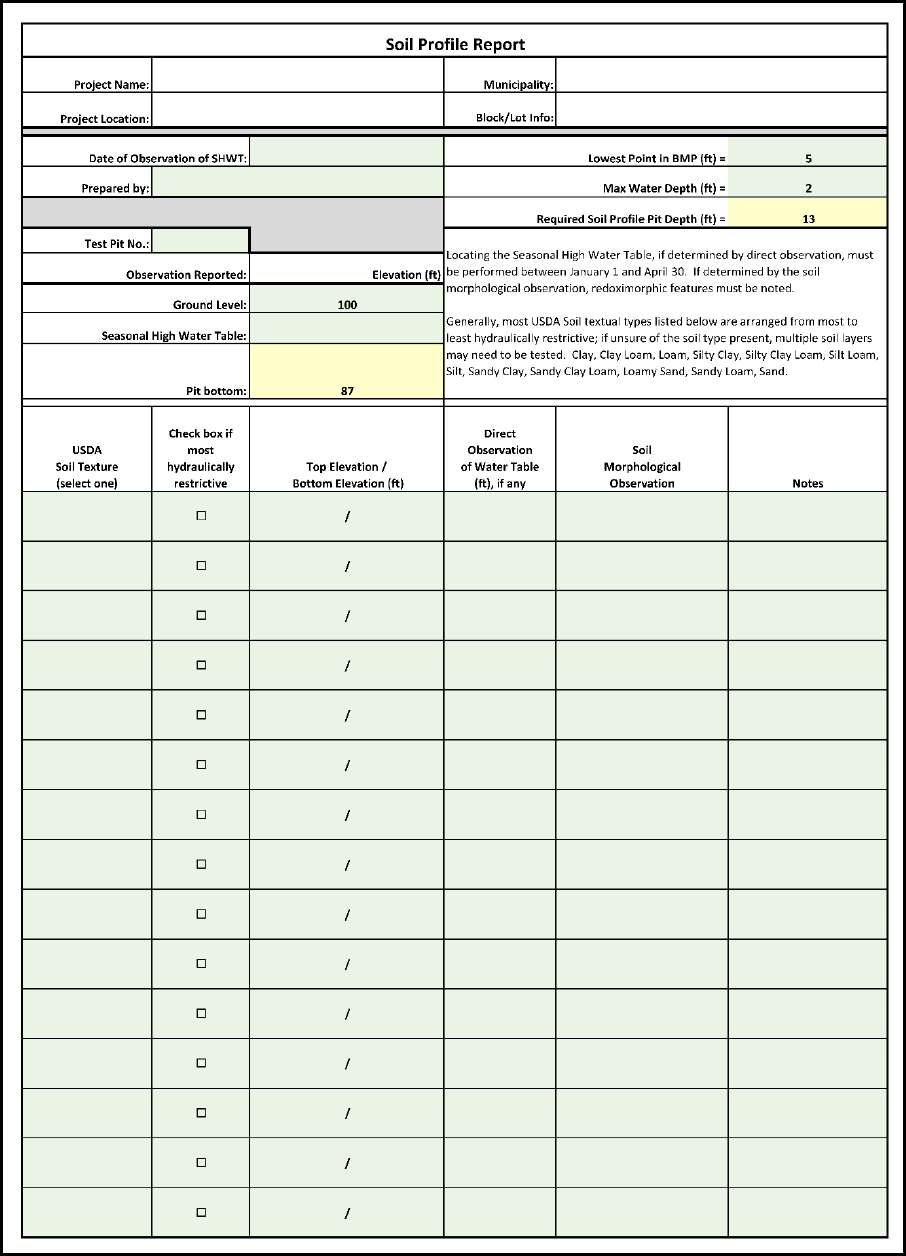
On Page 26, Figure 12-8 depicts an example of an Excel spreadsheet created to serve as a template for a
soil profile report. The workbook including this spreadsheet may be downloaded from the Department
website, under the heading for Chapter 12 of the BMP Manual, at:
https://dep.nj.gov/stormwater/bmp-manual/
Project: _________________________ Date: ___________
Soil Log #____ Prepared by: ___________
New Jersey Stormwater Best Management Practices Manual March 2024
Chapter 12: Soil Testing Criteria Page 25
Figure 12-7: Pineland Commission Soil Cross-Section Design Example
New Jersey Stormwater Best Management Practices Manual March 2024
Chapter 12: Soil Testing Criteria Page 26
Figure 12-8: Soil Profile Report Template
New Jersey Stormwater Best Management Practices Manual March 2024
Chapter 12: Soil Testing Criteria Page 27
Section 3: Soil Hydraulic Conductivity Testing
Subsection 3a: Acceptable Soil Hydraulic Conductivity Test Methods
A minimum of one soil hydraulic conductivity test must be performed at each soil profile pit and soil boring
location for infiltrating BMPs. Soil hydraulic conductivity can be determined as described in the
Addendum, which begins on Page 31, using a tube permeameter test, a percolation test, a single ring
infiltration test, or a basin flooding test (for fractured bedrock). Additional methods of establishing the
soil hydraulic conductivity, such as ASTM D3385 – Standard Test Method for Infiltration Rate of Soils in
Field Using Double-Ring Infiltrometer, and USBR 7300-89 – Well Permeameter Method, or other soil
hydraulic conductivity tests that utilize in-situ conditions and are accompanied by a recognized published
source reference can be used.
When performing a soil boring during the soil exploration, undisturbed soil sampling must be performed
and reported for any laboratory based test. All sampling must be continuous for the entire depth of the
soil boring to fully characterize the soil profile. Soil boring practice, such as ASTM – D6151 Using Hollow-
Stem Augers for Geotechnical Exploration and Soil Sampling, can provide a continuous drilling and
sampling method. ASTM D1587 – Thin-Walled Tube Sampling of Fine-Grained Soils for Geotechnical
Purposes can provide undisturbed soil sample for the hydraulic conductivity rate test in laboratory. More
soil boring information can be found at ASTM D6169 – Selection of Subsurface Soil and Rock Sampling
Devices for Environmental and Geotechnical Investigations and ASTM D6286 – Standard Guide for
Selection of Drilling and Direct Push Methods for Geotechnical and Environmental Subsurface Site
Characterization.
Subsection 3b: Hydraulic Conductivity Testing in Fractured Bedrock
When bedrock is encountered or known to exist below the proposed location of an infiltration BMP, the
basin flooding test may be conducted to ascertain the suitability of the location for the proposed BMP.
This test is not used to determine a numerical value for the saturated hydraulic conductivity rate of the
fractured bedrock and is, instead, a pass/fail test. This means that if the test area fails to drain completely
when following the method and timeframe provided in the Addendum, the fractured bedrock does not
meet the minimum requirement for the infiltration of stormwater runoff ,and also that an infiltration BMP
cannot be used in this location. Conversely, if the test area passes the basin flooding test, an infiltration
BMP that is designed with a maximum water depth of three feet for the largest design storm it will receive
is permitted on the test location, because the passing of the basin flooding test establishes an assumption
that the 3-foot depth of water in the infiltration BMP can be drained in 72 hours.
New Jersey Stormwater Best Management Practices Manual March 2024
Chapter 12: Soil Testing Criteria Page 28
Section 4: Construction and Post-Construction Oversight and Soil
Hydraulic Conductivity Testing
Subsection 4a: Construction and Post-Construction Oversight Requirements
During construction, regular oversight must be provided by the professional engineer responsible for
ensuring the effectiveness of infiltration BMPs to establish that the basin will function as designed.
Oversight includes, but is not limited to, the following:
Participation in a pre-construction meeting with the contractor to ensure all parties are familiar with
the special care necessary in constructing an infiltration BMP.
Confirmation of the proper use of construction equipment, especially to minimize the compaction of
the infiltration area.
Ensuring that the earthwork does not occur within the BMP area when the soil moisture content is
above the lower plastic limit and that the specifications of any replacement soil(s) is/are met.
Testing each soil layer where the hydraulic conductivity is critical, prior to the placement of a new
layer, to ensure that the hydraulic conductivity has been protected. For example, in bioretention –
infiltration basins, the subsoil must be tested prior to the placement of the soil filter media.
Ensuring that proper precautions are taken to prevent sediment entering the infiltration area during
construction or where unavoidable, if the basin is used as a sedimentation basin, excavation for the
sediment basin is at least 2 feet above the final design elevation of the basin bottom.
Subsection 4b: Post-Construction Hydraulic Conductivity Testing
Post-construction soil hydraulic conductivity tests must be conducted for infiltration BMPs to ensure that
the installed BMP functions as designed. Such testing must be carefully undertaken when all BMP
construction that may affect soil hydraulic conductivity has been completed. This includes the use of all
construction equipment and the placement of all construction material that may affect soil hydraulic
conductivity. In addition, hand tools and manual permeability test procedures must be used to avoid
affecting soil hydraulic conductivity.
Required Number of Tests
The number of soil hydraulic conductivity tests must follow the same requirements as the requirements
for the pre-construction soil hydraulic conductivity tests.
Required Test Depth
The post-construction hydraulic conductivity test must be conducted at the bottom of the excavation of
the BMP before the sand layer or soil bed is placed into the BMP.

New Jersey Stormwater Best Management Practices Manual March 2024
Chapter 12: Soil Testing Criteria Page 29
Permitted Test Methods
Only the single ring infiltration test, the modified basin flooding test and the double ring infiltration test
or a similar test that does not require a test hole in the soil layer are allowed. The tested soil hydraulic
conductivity from the post-construction hydraulic conductivity test must be equal or greater than the
tested soil hydraulic conductivity of the most restrictive soil layer that was tested in the pre-construction
condition.
All post-construction soil hydraulic conductivity test results must be certified by a licensed professional
engineer, submitted to the review agency and recorded in the as-built documents.
Section 5: Determination of the Input Parameters in Groundwater
Mounding Analyses
Input parameters for the Groundwater Mounding Analyses
In accordance with Chapter 13: Groundwater Table Hydraulic Impact Assessments for Infiltration BMPs,
a groundwater mounding analysis, when performed using the Hantush Spreadsheet, requires the user to
input the appropriate soil and geological parameters, which include the recharge rate, specific yield,
horizontal hydraulic conductivity and the initial thickness of the saturated zone. These parameters are
discussed below.
Recharge Rate
The recharge rate, R, is the design hydraulic conductivity of the most restrictive soil layer below the
proposed infiltration BMP as described in Section 2a, and, in particular, the paragraph entitled, “Location
for soil samples or in-situ tests of the soil hydraulic conductivity,” found on Page 19, of this chapter.
Specific Yield
The default value for specific yield, S
y
, is 0.15, but other values equal to or less than 0.2 can be used if
testing of the soil within the proposed infiltration BMP is conducted. No value greater than 0.2 can be
used, regardless of whether a higher value for specific yield is obtained from the soil testing results.
In the soil science field, specific yield is what remains when the field capacity is subtracted from the
porosity of a particular soil, i.e.:
Specific yield = porosity – field capacity
The acceptable soil testing methods for determining the porosity and the field capacity are in the Soil
Survey Investigations Report No. 42, Kellogg Soil Survey Laboratory Methods Manual, published by NRCS.
The manual is available online at:
https://www.nrcs.usda.gov/sites/default/files/2022-10/SSIR42-v6-pt1.pdf
New Jersey Stormwater Best Management Practices Manual March 2024
Chapter 12: Soil Testing Criteria Page 30
Note that the specific yield values obtained from literature reviews or textbooks cannot be substituted
for the value obtained from soil testing conducted within the proposed infiltration BMP.
Horizontal Hydraulic Conductivity
Horizontal hydraulic conductivity, K
h
, is an essential parameter affecting the volume and speed of
stormwater runoff that has infiltrated to move away from the center of the infiltration BMP during the
infiltration period. However, horizontal conductivity may be affected by factors other than the soil types,
e.g., the stratification of soil layers. The determination of horizontal hydraulic conductivity requires
several test wells to observe horizontal flows in various directions under the aquifer test and also requires
analysis through complicated analytic models. Therefore, conducting field tests in a proposed
development site to determine horizontal hydraulic conductivity is not recommended. The default values
listed in Chapter 13 are to be used.
Initial Thickness of Saturated Zone
The initial saturated zone thickness, hi(0), is also an essential factor affecting the mounding height. The
thickness of the unsaturated zone (not accounting for the capillary fringe) can also be described as the
thickness of the water table below the land surface. If a value greater than 10 ft is used, it must be
accompanied by on-site testing results that demonstrate the value used is appropriate. The input value
must never exceed 75 ft, which is based on the preliminary results of research conducted by the USGS.
The exact maximum allowed value may be subject to revision based on the final results of the research.
Any on-site boring used to justify a value greater than 10 ft must be a continuous sampling boring for the
entire drilled depth.

New Jersey Stormwater Best Management Practices Manual March 2024
Chapter 12: Soil Testing Criteria Page 31
ADDENDUM
This addendum provides the Department summary of the NRCS guidance documents to establish
hydrologic soil group based on hydraulic conductivity and the procedures for a percolation test, a tube
permeameter test and a basin flooding test, which was mentioned in Section 3b above.
Part A: Procedures for Soil Hydraulic Conductivity Testing
Test procedures for each of the testing methods cited in Section 3 above are found beginning on the pages
specified below.
Hydraulic Conductivity Test Procedures
Subsection
No.
Test Name
Page
No.
A1 Percolation Test 32
A2 Tube Permeameter Test 37
A3 Basin Flooding Test 44
A4 Modified Basin Flooding Test 45
A5 Single Ring Infiltration Test 47
New Jersey Stormwater Best Management Practices Manual March 2024
Chapter 12: Soil Testing Criteria Page 32
Subsection A1: Percolation Test
A percolation test can be utilized to establish the hydraulic conductivity of soils provided that
percolation test results are converted to hydraulic conductivity in accordance with Item 5, which is
located beginning on Page 34.
Percolation tests must not be conducted in frozen ground or in holes which have been allowed to
remain open to the atmosphere for periods greater than three days.
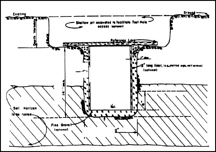
The required configuration of the test hole is illustrated in Figure 12-9, below.
Figure 12-9: Percolation Test Configuration
1. Equipment Requirements
The following equipment is required for the percolation test:
a. A soil auger, post-hole digger or other means of preparing a test hole as prescribed below,
b. A knife or trowel for removing smeared or compacted surfaces from the walls of the test hole,
c. Fine (from 2 to 10 millimeter in diameter) gravel (optional),
d. A water supply (50 gallons is generally adequate),
e. A straight board (to serve as fixed reference point for water level measurements),
f. A clock and a ruler (12 inches or longer, engineering scale),
g. An automatic siphon or float valve (optional) and
6 to 12
ih
0.5
inch
0.5
inch
Max.
14 inches
New Jersey Stormwater Best Management Practices Manual March 2024
Chapter 12: Soil Testing Criteria Page 33
h. A hole liner, at least 12 inches in height, consisting of a stiff tubular material, such as section
of slotted pipe or well screen, or a section of one – quarter inch hardware cloth, or other
similar material, rolled into a tube. The hole liner must be no smaller than 2 inches in
diameter less than that of the test hole.
2. Test Hole Preparation
The test hole shall be prepared in accordance with the following list, in the order each step
appears:
a. Step One: Excavate a test hole with horizontal dimensions of 6 to 12 inches at a depth such
that the lower 6 inches of the test hole are contained entirely within the soil horizon or layer
of fill material being tested. In order to facilitate access to the lower portion of the hole, the
test hole may be excavated from the bottom of a shallow pit provided that the vertical axis of
the test hole is a minimum of 14 inches measured from the bottom of the pit to the bottom
of the test hole.
b. Step Two: In soil textures other than sands or loamy sands, remove smeared or compacted
soil from the sides and bottom of the test hole by inserting the tip of a knife or trowel into
the soil surface and gently prying upward and outward. Remove loose soil from the test hole.
c. Step Three: At this point, a 0.5 inch layer of fine gravel may be placed in the bottom of the
hole to protect the soil surface from disturbance or siltation when water is added to the hole.
If additional protection is desired, a hole liner as described in 1.h. above may be placed in the
hole and the space between the liner and the sides of the hole may be filled with fine gravel.
d. Step Four: Place and secure a straight board horizontally across the top of the test hole, as
shown in Figure 12-9, to serve as a fixed point for depth of water measurements to be made
at appointed time intervals throughout the test.
3. Pre-Soaking of Soils
a. All soils, except for sandy textured soils which meet the requirements in 3.b. below, shall be
pre-soaked using the following procedure. Any soil which exhibits cracks or fissures between
soil aggregates must be pre-soaked in the following manner regardless of the texture.
i. Fill the test hole with water and maintain a minimum depth of 12 inches for a period of 4
hours by refilling as necessary or by means of an automatic siphon or float valve.
ii. At the end of 4 hours, cease adding water to the hole and allow the hole to drain for a
period of duration ranging between 16 and 24 hours.
b. In sandy textured soils, including sands, loamy sands and sandy loams, where a rapid
percolation rate is anticipated, fill the test hole with water to a depth of 12 inches and allow
to drain completely.
i. Refill the hole to a depth of 12 inches and record the time required for the hole to drain
completely.
ii. If this time is less than 60 minutes, the test procedure may begin as prescribed in 4. Below
without further pre-soaking.

New Jersey Stormwater Best Management Practices Manual March 2024
Chapter 12: Soil Testing Criteria Page 34
iii. If water remains in the test hole after 60 minutes, the hole must be pre-soaked as
prescribed above before proceeding with the test.
4. Percolation Rate Determination
Immediately following the pre-soak procedure (no more than 28 hours after the start of the pre-
soak procedure), the percolation rate shall be determined using the following procedure, in the
order each step appears:
a. Step One: If water remains in the test hole after the completion of the pre-soak period, the
test must be terminated and the percolation rate shall be reported as greater than 60 minutes
per inch.
i. If no water remains in the test hole, fill to a depth of 7 inches.
ii. After the water level drops to a depth of 6 inches, start the recording of the time interval
for the drop in water level from 6 inches to the nearest one tenth of an inch in the test
hole.
iii. Refill the hole at the end of each time interval and repeat this procedure using the same
time interval until a constant rate of fall is attained, which occurs when the difference
between the highest and lowest values for three consecutive measurements is no greater
than two tenths of an inch.
b. Step Two: Immediately after the completion of “Step One,” refill the test hole to a depth of 7
inches or more. The time recording shall be started when the water level drops to 6 inches
and stopped when the water in the hole has been emptied. This time divided by 6 will be the
percolation rate in minutes per inch.
5. Soil Hydraulic Conductivity Determination
The soil hydraulic conductivity shall be established from the results of the percolation rate based
on the following procedures. When the purpose of the test is to determine the soil hydraulic
conductivity at the level of infiltration, the slowest percolation rate determined shall be used as
a field measured percolation rate. If any of the measured percolation rates are slower than 60
minutes per inch, then this method shall not be utilized.
For circular holes, the field measured hydraulic conductivity value shall be calculated using
Equations 1 and 2 below:
P
=
(Equation 1)
K
s
=
( )
(Equation 2)
where:
P
is the percolation rate (min/in),
A is the surface area of the bottom of the test hole (sq in),
t = the time water drops for 6 inches of water (min),
New Jersey Stormwater Best Management Practices Manual March 2024
Chapter 12: Soil Testing Criteria Page 35
K
s
is the saturated soil hydraulic conductivity (in/hr) and
is the diameter of the test hole (in).
a. Since the test measures the time for 6 inches of water to empty from a circular hole,
Equations 1 and 2 can then be simplified as shown below:
P
=
K
s
=
where, represents the right half of Equation 2. Thus, for various values of , is
calculated as shown in Table 12-9 below:
Table 12-9: Values for Corresponding Test Hole Diameters
Parameter
Values
(in)
6
8
9
10
11
12
20.00
24.00
25.71
27.27
28.70
30.00
b. If the test is performed in a rectangular or square hole, Equation 2 is modified as
follows:
P
=
(Equation 1)
K
=
[
(
)
]
(Equation 2 modified)
where:
is the length of the test hole and
is the width of the test hole.
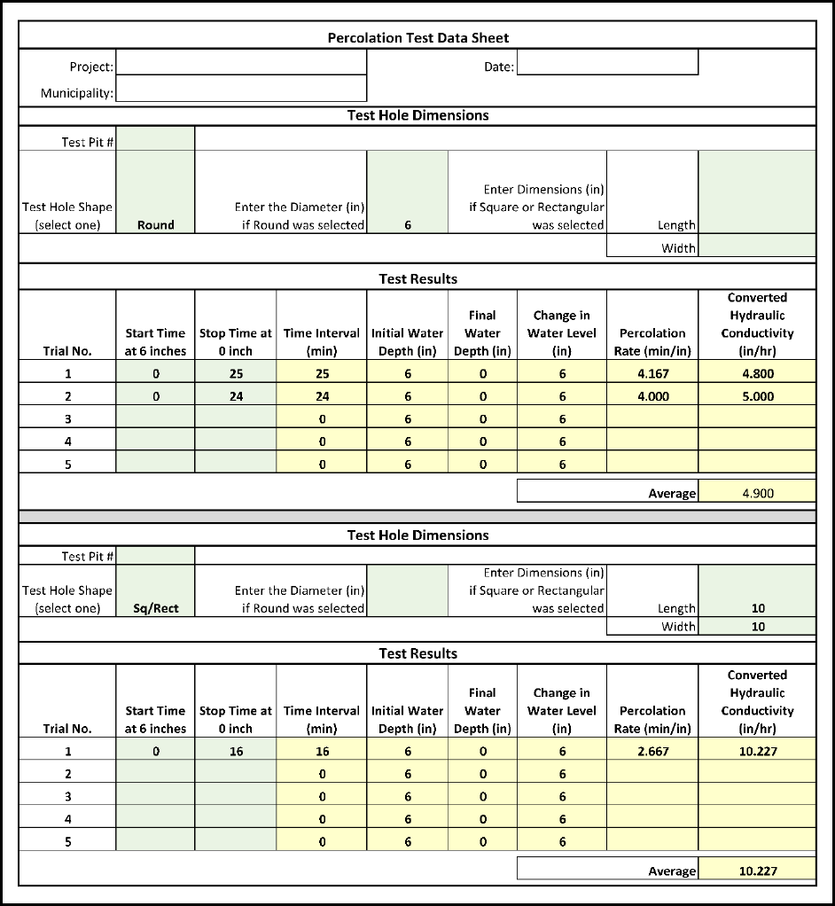
On the following page is an example of an Excel spreadsheet that may be used for the conversion
of the percolation rate to the soil hydraulic conductivity, in Figure 12-10. The workbook including
this spreadsheet may be downloaded from the Department website, under the heading for
Chapter 12: Soil Testing Criteria, at:
https://dep.nj.gov/stormwater/bmp-manual/
New Jersey Stormwater Best Management Practices Manual March 2024
Chapter 12: Soil Testing Criteria Page 36
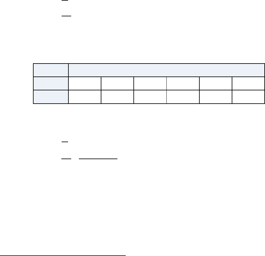
Figure 12-10: Percolation Test Data Sheet
New Jersey Stormwater Best Management Practices Manual March 2024
Chapter 12: Soil Testing Criteria Page 37
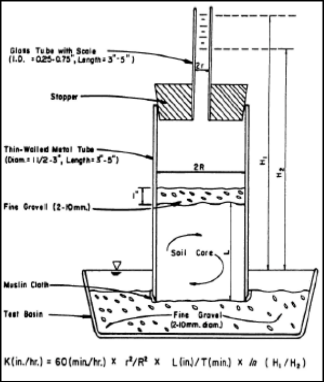
Subsection A2: Tube Permeameter Test
An in-situ Tube Permeameter test (depicted in Figure 12-11 below) can be utilized to establish the soil
hydraulic conductivity in accordance with the procedures below. Take note: the tube permeameter
test can only be used only when undisturbed samples can be collected.
Figure 12-11: Tube Permeameter (with Standpipe)
1. Equipment Requirements
The following equipment is required for performing a tube permeameter test:
a. A thin-walled (1 millimeter or less in thickness) metal tube, from 1.5 to 3 inches in diameter,
6 inches in length and beveled on the lower outside edge,
b. A wooden block with dimensions broader than the diameter of the tube in the previous item
above, plus a hammer to drive the tube into the soil,
c. A small trowel,
d. A knife to trim the core,
New Jersey Stormwater Best Management Practices Manual March 2024
Chapter 12: Soil Testing Criteria Page 38
e. Muslin or similar open-textured cloth and a rubber band,
f. A soaking basin of adequate size and depth to soak the cores as prescribed in 2.d. below,
g. Fine gravel (from 2 to 10 millimeters in diameter),
h. A test basin of adequate length (generally 10 inches or greater) and width (generally 4 inches
or greater) to accommodate one or more replicate samples at a time. The depth of the basin
should be adequate to allow placement of the sample on a layer of gravel while keeping the
bottom of the core several inches below the rim of the basin, as prescribed in 2.d. below (See
Figure 12-11),
i. A stopper which fits water-tight into the top of the sample tube and which is fitted with a
glass standpipe from 3 to 5 inches long and from 0.25 to 0.75 inches in diameter (See Figure
12-11). The standpipe should have a scale for measuring changes in water level over time as
required in 3.b. below,
j. A small laboratory wash bottle for refilling standpipe,
k. A clock or watch with second hand,
l. A ruler (with preferably 1:10 engineering scale demarcations and
m. One gallon of water per test. The water should be allowed to stand in an open container until
clear of dissolved air. Boiling may be used to remove air provided that the water is allowed
to cool down to room temperature before use.
2. Sample collection and preparation
Only undisturbed samples are permitted for the test. The samples shall be collected in accordance
with the following:
a. Samples shall be collected as prescribed in 2.c. below.
i. When the texture of the soil to be tested is sand or loamy sand, if there is a lack of soil
cohesion or the presence of large amounts of coarse fragments, roots or worm channels
prevent the taking of undisturbed samples, the tube permeameter test must not be
used.
ii. When the texture of the soil is other than sand or loamy sand and undisturbed samples
cannot be taken, the tube permeameter test shall not be used.
b. When the tube permeameter test is used, a minimum of 2 replicate samples must be taken
and the procedures outlined in this section shall be followed for each replicate sample to be
tested.
i. It is recommended that more than 2 replicate samples be taken to avoid the necessity of
re-sampling in the event that samples are damaged in transport or the results of one or
more replicate tests must be rejected due to extreme variability of results, as required in
New Jersey Stormwater Best Management Practices Manual March 2024
Chapter 12: Soil Testing Criteria Page 39
4.b. below.
ii. Replicate samples shall be taken from within the same soil horizon at the same location
within the area of interest.
c. The following procedure shall be used to collect each replicate sample:
i. Step One: Expose an undisturbed horizontal surface within and a minimum of 3 inches
above the bottom of the soil horizon or layer to be tested.
ii. Step Two: Position the sampling tube on the soil surface at the point chosen for sampling.
Care should be taken to avoid large gravel or stones, large roots, worm holes or any
discontinuity which might influence results.
If the soil is excessively dry it may be moistened, but not saturated, provided that the
force of falling water is not allowed to act directly upon the soil surface.
iii. Step Three: Hold the wooden block on the top of the sampling tube and drive the tube
into the soil a distance of 2 to 4 inches (but not entirely through the horizon) using light
even blows with the hammer.
Care should be taken to hit the block squarely in the center and to drive the tube
straight down into the soil.
Do not attempt to straighten the tube by pushing or by hitting the tube on the side
with the hammer.
iv. Step Four: When the tube has been driven to the desired depth, carefully remove the soil
around the outside of the tube, insert a trowel into the soil below the tube and, exerting
pressure from below, lift the sampling tube out of the soil.
v. Step Five: Trim the bottom of the soil core flush with the sampling tube using a knife and
taking care not to smear the soil surface.
Carefully invert the sampling tube and tap the side lightly with the handle of the knife
or similar implement to remove any loose soil which may be resting on the top of the
soil core and to verify that an undisturbed sample has been obtained.
Omit this step in the case of sandy-textured non-cohesive soils with single grain
structure.
Check the top and bottom surfaces of the core sample and discard any sample which
has worm holes or large cracks caused by handling.
vi. Step Six: After the core has been checked for worm holes or signs of disturbance, stretch
a piece of muslin cloth over the bottom of the tube and secure with a strong rubber band.
d. The following procedure shall be used for pre-soaking undisturbed core samples for the
tube permeameter test:
i. Step One: Place the soil core in the pre-soak basin and fill the basin with water to a point
New Jersey Stormwater Best Management Practices Manual March 2024
Chapter 12: Soil Testing Criteria Page 40
just below the top of the soil core.
Never fill the basin to a level which is higher than the top of the soil core.
Never use water directly from the tap to soak cores.
Use only de-aired water as prescribed in ‘m’ in the equipment requirements section
above.
Allow the sample to soak until the top surface of the core is saturated with water.
This may require only a few minutes of soaking for sandy textured soils or several
days for clay textured soils.
Failure to soak the sample for sufficient time may result in greatly reduced soil
hydraulic conductivity measurements due to entrapped air.
ii. Step Two: When the sample has soaked for sufficient time, place a 1 inch layer of fine
gravel (from 2 to 10 millimeters in diameter) on top of the soil core in the sampling tube.
Slowly fill the tube with de-aired water taking care not to disturb the surface of the
core.
A small spatula or similar implement may be used to break the fall of the water as it
is poured into the tube.
iii. Step Three: Immediately transfer the soil core to the test basin in which a layer of gravel
has been placed and gently press the soil core into the gravel so that it stands vertically
with its base positioned at the desired depth below the rim of the test basin.
3. Tube Permeameter Testing Procedure
The following procedure shall be used to conduct the tube permeameter test:
a. Step One: When the soil core has been positioned at the desired height within the test basin
(see Figure 12-11), fill the test basin to overflowing with de-aired water.
i. Note: The hydraulic head used in the test depends upon the height of the top of the
sample tube or standpipe above the rim of the test basin as shown in Figure 12-11.
ii. In general, a higher hydraulic head should be used for heavy textured soils to expedite
the test and a lower head should be used for sandy textured soils to prevent an
excessively fast flow rate.
b. Step Two: Fill the tube to overflowing with de-aired water and record the time, in minutes,
required for the water level in the tube to drop a standard distance, e.g., 0.5, 1 or 2 inches.
i. Repeat this step until the rate of fall becomes constant or the difference between the
highest and lowest of three successive readings is less than five percent.
ii. When the readings are less than 20 minutes in length the time should be reported to the
nearest second.

New Jersey Stormwater Best Management Practices Manual March 2024
Chapter 12: Soil Testing Criteria Page 41
Alternate Step Two: When the rate of fall observed in "Step Two" is slow, the flow rate may
be increased by use of a standpipe as shown in Figure 12-11.
i. Carefully insert the standpipe into the top of the sample tube and fill with de-aired water.
ii. The apparatus should be checked for leaks where the standpipe fits into the sample tube.
Silicon jelly, petroleum jelly or a similar material may be used to prevent leakage.
iii. Measure the rate of fall of the water level in the standpipe as in Step Two.
4. Determination
The soil hydraulic conductivity shall be established from the results of the Tube permeameter test
based on the following procedures.
a. Step One: The soil hydraulic conductivity of each replicate sample tested shall be calculated
using the following formula:
K = 60 min/hr
[
ln
(
)
]
where:
K is the soil hydraulic conductivity of the soil sample (in/hr),
is the length of the soil core (in),
H
1
is the height of the water level above the rim of the test basin at the beginning of each
test interval (in),
H
2
is the height of the water level above the rim of the test basin at the end of each test
interval (in),
is the time required for the water level to drop from H1 to H2 during the final test interval
(min),
is the radius of the standpipe (either cm or in) and
is the radius of the soil core (also either in cm or in and matching the units used for ). Note
that when the standpipe is not used,
= 1.
Lastly, “ln” is the abbreviation for the natural logarithm.
b. Step Two: The variability of test results shall be evaluated as follows:
i. The variability of soil hydraulic conductivity test results shall be considered acceptable
only where the results of all replicate tests fall within 1 soil hydraulic conductivity class or
2 adjacent permeability classes. Soil hydraulic conductivity classes are defined by their
respective range of hydraulic conductivities, as depicted on the following page in Table
12-10. Note that Table 12-10 does not imply that it is acceptable to use a Soil Permeability
Class Rating Test to measure soil hydraulic conductivity.

New Jersey Stormwater Best Management Practices Manual March 2024
Chapter 12: Soil Testing Criteria Page 42
Table 12-10: Soil Hydraulic Conductivity Classes
Measured Hydraulic Conductivity
(in/hr)
Soil Hydraulic
Conductivity Class
Greater than or equal to 20 K5
6 – 20
K4
2 – 6
K3
0.6 – 2
K2
0.2 – 0.6 K1
Less than 0.2 K0
ii. Where the results of replicate tests differ by more than one soil hydraulic conductivity
class, the samples must be examined for the defects listed below. If any of these defects
are found, the defective core(s) must be discarded and the test repeated using a new
replicate sample for each defective replicate sample.
Cracks, worm channels, large root channels or poor soil tube contact within the
sample yielding the highest soil hydraulic conductivity value(s),
Large pieces of gravel, roots or unsaturated soil within the interior of the sample
yielding the slowest soil hydraulic conductivity value(s) and
Smearing or compaction of the upper or lower surface of the sample yielding the
lowest soil hydraulic conductivity value(s).
c. Step Three: When test results have been obtained with an acceptable range of variability as
defined in “Step Two” above, the results shall be interpreted as follows:
i. When the purpose of the test is to determine the design soil hydraulic conductivity at the
level of infiltration, the slowest of the test replicate results shall be used for design
purposes.
ii. When the purpose of the test is to identify a hydraulically restrictive horizon or
substratum above the water table, the horizon or substratum in question shall be
considered hydraulically restrictive if the average soil hydraulic conductivity of the
replicate samples tested falls within soil hydraulic conductivity class K0 as defined in i of
“Step Two” above.
iii. When the purpose of the test is to identify an excessively coarse horizon or substratum
above the water table, the horizon or substratum in question shall be considered
excessively coarse if the average hydraulic conductivity of the replicate samples tested
falls within soil hydraulic conductivity class K5 as defined in i of “Step Two” above.
d. Step Four: Where results of replicate tests exceed the limits of variability allowed in i of “Step
Two” above, the results shall be interpreted as follows:
New Jersey Stormwater Best Management Practices Manual March 2024
Chapter 12: Soil Testing Criteria Page 43
i. When the purpose of the test is to determine the design soil hydraulic conductivity at the
depth of infiltration, the slowest of the test replicate results must be used for design
purposes.
ii. When the purpose of the test is to identify a hydraulically restrictive horizon or
substratum above the water table, the horizon or substratum in question shall be
considered hydraulically restrictive if the slowest soil hydraulic conductivity of the
replicate samples tested falls within soil hydraulic conductivity class K0 as defined in i of
“Step Two” above.
iii. When the purpose of the test is to identify an excessively coarse horizon or substratum
above the water table, the horizon or substratum in question shall be considered
excessively coarse if the fastest soil hydraulic conductivity of the replicate samples tested
falls within soil hydraulic conductivity class K5 as defined in i of “Step Two” above.
Alternative Tube Permeameter Tests
ASTM D2434 Standard Test Methods for Measurement of Hydraulic Conductivity of Coarse-Grained
Soils and ASTM D5084 Standard Test Methods for Measurement of Hydraulic Conductivity of Saturated
Porous Materials Using a Flexible Wall Permeameter can be used as the Tube Permeameter Test to be
performed in a soil laboratory, subject to the following conditions:
Soil sample shall be taken by undisturbed soil sampling methods as stated on Page 39, under Item 2.c.
Preservation and transportation of the soil sample must follow ASTM D4220 Standard Practices for
Preserving and Transporting Soil Samples.
Intact soil specimens from undisturbed soil samples must be used. Reconstitution, remolding or
compaction of the soil specimen is not allowed, but a trimming of the soil specimen edges or surfaces
to fit the tube wall or the porous end pieces is permitted.
For ASTM D2434, Method A (rigid wall) and Method B (flexible wall) can be used. Single- or dual-ring
type of permeameter can be used. The selected method and type of permeameter shall be the one
that can generate the most accurate results based on the soil types and the instructions in the ASTM
method.
For ASTM D5084, only Method A (constant head), Method B (falling head, constant tailwater elevation)
and Method C (falling head, rising tailwater elevation) can be used. The selected method shall be the
one that can generate the most accurate results based on the soil types and the instructions in the
ASTM method.
The testing procedures, raw data and results must be logged and shown in the soil report.
New Jersey Stormwater Best Management Practices Manual March 2024
Chapter 12: Soil Testing Criteria Page 44
Subsection A3: Basin Flooding Test
A basin flooding test can be utilized, in accordance with the procedures below, to establish whether
fractured bedrock is present.
This is a “Pass” or “Fail” test. A basin flooding test can only be used to determine the bedrock that is
situated within eight feet below the lowest elevation of the proposed BMP bottom or to within the depth
that is at least twice the maximum potential water depth generated by the largest design storm,
whichever is greater. If the bedrock is beyond the abovementioned depth, the basin flooding test cannot
be used.
The basin flooding test must not be conducted in rock strata which have been blasted with explosives.
Due to the potential safety hazards which are posed by the excavation of a large test basin such as
that required for this test, adequate safety measures must be taken to comply with all applicable
Federal, State and local laws and regulations governing occupational safety.
□ Access to the test basin during the test procedure is permitted when conditions are safe.
□ Care must be taken and include the use of warning signs or a fence to limit access to the basin by
the public during periods when the basin is left unattended, or both, as a minimum precaution.
1. Equipment Requirements
The following equipment is required for performing a basin flooding test:
a. Excavating equipment capable of producing a test basin as prescribed in 2 below,
b. Water supply (minimum of 375 gallons per basin filling) and
c. A means for accurately measuring the water level within the basin as required in 3 below.
2. Test Basin Preparation
The test basin must be prepared in accordance with the following requirements. A test basin
meeting all of the following requirements shall be excavated within or immediately adjacent to
the infiltration area of the proposed BMP.
a. The bottom of the test basin shall be on the bedrock substratum that is within the depth of
eight feet below the lowest elevation of the proposed BMP bottom or a depth that is at least
twice the maximum potential water depth generated by the largest design storm, whichever
is greater, but not below the seasonal water table.
b. The bottom area of the test basin must be a minimum of 50 square feet and the depth of the
basin must be greater than 12 inches,
c. The bottom of the basin must be made as level as possible so that high areas of rock do not
project above the water level when the basin is flooded as prescribed in 3 below and
d. If groundwater is observed within the test basin, the basin flooding test must not be used.
New Jersey Stormwater Best Management Practices Manual March 2024
Chapter 12: Soil Testing Criteria Page 45
3. Basin Flooding Test Procedure
The following procedure must be used to conduct the Basin Flooding test:
a. Step One: Fill the test basin with exactly 12 inches of water and record the time.
i. Allow the basin to drain completely.
ii. If the time required for the basin to drain completely is greater than 24 hours, the test
shall be terminated and the limiting zone in question shall be considered to be a massive
rock substratum.
b. Step Two: If the basin drains completely within 24 hours after the first flooding, immediately
refill the basin to a depth of 12 inches and record the time.
If the basin drains completely within 24 hours of the second filling, the limiting zone in question
shall be considered to be fractured rock substratum for the design of an infiltration BMP.
Interpretation of Results
If the result takes longer than 24 hours to drain after either the first or second instance of filling,
(from Step One or Step Two above, respectively), the underlying bedrock is not suitable for the
placement of an infiltration BMP in this location and the test results shall be listed as "Failed."
Conversely, if the test results from Step Two above indicate a fractured rock substratum is present,
no numerical value of saturated hydraulic conductivity shall be used. Only when the test results
from Step Two indicate fractured rock substratum is present may an infiltration BMP be installed at
the test location, provided the maximum depth of runoff for the largest design storm to be received
by said infiltration BMP does not exceed 3 feet. Only when this depth of runoff limitation is used
in the design and when the test results indicate a fractured rock substratum is present, may the
assumption be made that the infiltration BMP will be able to drain within 72 hours.
Subsection A4: Modified Basin Flooding Test
This test is intended for testing the soil hydraulic conductivity of BMPs that infiltrate runoff into subsoil,
under post-construction conditions.
Due to the potential safety hazards which are posed by the test basin and ponding water required for this
test, adequate safety measures must be taken in accordance with N.J.A.C. 7:9A.
Access to the test basin during the test procedure is permitted when conditions are safe.
Care must be taken and include the use of warning signs and a fence to limit access to the basin by
the public during periods when the basin is left unattended.
1. Equipment Requirements
The following equipment is required for performing a Modified Basin Flooding test:
a. A supply of water,

New Jersey Stormwater Best Management Practices Manual March 2024
Chapter 12: Soil Testing Criteria Page 46
b. A means for accurately measuring the water level within the BMP as required in 3 below and
c. A timepiece or timer to record the lapse of time.
2. Test BMP Preparation
The post-construction hydraulic conductivity test must the conducted at the bottom of the
excavation of the BMP before the sand layer or soil bed is placed into the BMP.
If ponding water is observed in the BMP, when no precipitation occurred within 72 hours prior
to the observation of the ponding water in the BMP, the modified basin flooding test shall not
be used and the BMP shall be determined to fail the test.
3. Modified Basin Flooding Test Procedure
a. Step One: Fill the test BMP with 1/3 of the maximum designed water depth above the lowest
excavated elevation and record the time. Allow the BMP to drain to the lowest excavated
elevation completely. If the time required for the BMP to drain completely is greater than 24
hours, the test shall be terminated and the green infrastructure BMP shall be determined to
have failed to drain.
b. Step Two: If the BMP drains completely within 24 hours after the first flooding, immediately
refill the BMP to 1/3 of the
maximum designed water depth and record the time.
4. Soil Hydraulic Conductivity Determination
The soil hydraulic conductivity is calculated using the following equation:
K
s
=
(
.
)
where:
K
s
is the saturated soil hydraulic conductivity (inch/hour),
is the volume occupied by the 1/3 of the maximum designed water depth in the BMP (cubic
feet),
is the time to drain the BMP (hours),
is the surface area of the bottom of the BMP (square feet) and
is the surface area of the sides of the BMP for the 1/3 of the maximum designed water
depth (square feet)
For example, a BMP with an infiltration bottom area measuring 10 feet by 5 feet and a 2 feet of
maximum design,
= 50 square feet. The value for
is equal to the sum of 2 sides measuring
10 feet in length plus 2 sides measuring 5 feet in length, which is then multiplied by the 1/3 of the
2 feet depth, i.e.,
= 2 (10 ft +5 ft) (2 ft)/3 = 20 square feet.
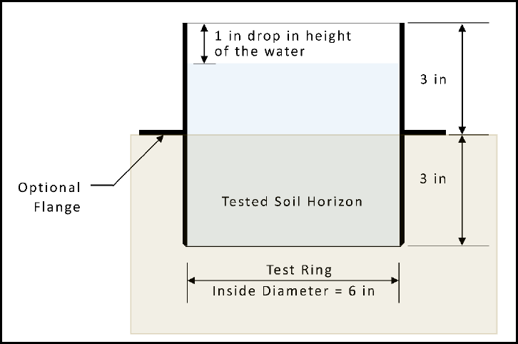
New Jersey Stormwater Best Management Practices Manual March 2024
Chapter 12: Soil Testing Criteria Page 47
Subsection A5: Single Ring Infiltration Test
A Single Ring Infiltration test may be used to establish the soil hydraulic conductivity of soils in
accordance to the procedures below.
Single Ring Infiltration tests must not be conducted in frozen ground nor in holes which have been
allowed to remain open to the atmosphere for periods greater than three days.
The required configuration of the test is illustrated in Figure 12-12 below.
Figure 12-12: Single ring test configuration
1. Equipment Requirements
The following equipment is required for the Single Ring Infiltration test:
a. A 6 inch long beveled edge test ring with an inside diameter of 6 inches,
i. It is better if the test ring has an outer flange located 3 inches from the lower end of the
test ring in order to stop the test ring from penetrating more than 3 inches into the soil
layer.
ii. Better observations are made using a test ring that has a mark on the inner wall, located
1 inch below the top end. With this mark, there may not be a need for the ruler.
b. A leveler (a carpenter’s level is best),
c. A piece of filter fabric (at least 1.5 inches by 1.5 inches, but less than 3 inches by 3 inches),
d. A block of wood,
e. A hand sledgehammer,
New Jersey Stormwater Best Management Practices Manual March 2024
Chapter 12: Soil Testing Criteria Page 48
f. A small hand shovel (trowel),
g. A supply of water (50 gallons is generally adequate),
h. A stopwatch with an accuracy to at least one tenth of a second,
i. A ruler (12 inches or longer, engineering scale) and
j. Recording papers.
2. Test Location Preparation
The test location shall be prepared in accordance with the following steps:
a. Excavate the test pit to the soil layer to be tested. The tested soil layer must be the most
restrictive layer of the soil layers within the soil profile pit.
b. The surface of the soil shall be nearly level. However, do not compact the soil when leveling
the surface.
c. Remove any rock fragments that will prevent the test ring from being driven into the soil.
3. Test Procedure
a. Step One: Drive the test ring into soil
i. Place the block of wood on top of the test ring. Using the hand sledge and block of wood,
drive the test ring a depth of 3 inches into the test soil layer. Move the wood block around
the edge of the test ring top every one or two blows so that the test ring will penetrate
the soil uniformly. Do not shake or shift the test ring sideways so as to cause annular
space between the test ring and the soil surface surrounding the test ring, which may lead
to a leak of water from the annular space.
ii. Use a leveler to check whether the test ring is leveled.
iii. If the surface of the soil surrounding the wall of the test ring is only slightly disturbed,
tamp the disturbed soil adjacent to the inside and outside wall of the test ring until the
soil is as firm as it was prior to disturbance. If the surface of the soil surrounding the wall
of the test ring is excessively disturbed (signs of extensive cracking, excessive heave, and
the like), reset the test ring to other locations.
b. Step Two: Pre-soaking the soil
i. Place the piece of filter fabric on top of the soil in the center of the test ring.
ii. For sandy textured soils, including sands, loamy sands and sandy loams, where a rapid
infiltration rate is anticipated,
Place the ruler into the test ring if the test ring is not marked with a 1 inch mark.
New Jersey Stormwater Best Management Practices Manual March 2024
Chapter 12: Soil Testing Criteria Page 49
Gently and slowly add water from a position close to the piece of filter fabric resting
on the soil and slowly lift the water container as the water level rises. Fill the test ring
to the top with water.
Let the water drain completely.
iii. For other than sandy textured soils,
Place the ruler into the test ring if the test ring is not marked with a 1 inch mark.
Gently and slowly add water from a position close to the piece of filter fabric resting
on the soil and slowly lift the water container as the water level rises. Fill the test ring
to the top with water.
Let the water drain completely. If the elapsed time for the water level to drop to a
height of 1 inch is more than 60 minutes, stop timing.
c. Step Three: Observed Field Intake Rate Determination
Immediately following the pre-soak procedure, the Observed Field Intake Rate shall be
determined using the following procedure:
i. Gently and slowly add water from a position close to the piece of filter fabric resting on
the soil and slowly lift the water container as the water level rises. Fill the test ring to the
top with water.
ii. Start the stopwatch as soon as the water fills to the top of the test ring.
iii. Measure the elapsed time for the water to drop 1 inch. Record the elapsed time in each
test.
iv. Repeat steps i to iii until the elapsed time to drop 1 inch of water becomes stabilized. If
the difference between two measurements of the time is within five tenths of a second,
it is deemed stabilized.
v. The observed field intake rate (in/hr) is 1 inch divided by the stabilized elapsed time to
drop 1 inch of water.
vi. At least three observed field intake rates shall be observed before the test is ended.
vii. If the elapsed time to drop 1 inch of water is more than 1 hour for two consecutive tests,
the soil is deemed to have an observed field intake rate less than 1 in/hr and the test can
be ended.
4. Hydraulic Conductivity Determination
The observed field intake rate must be converted to the hydraulic conductivity by using the curve
found on the following page or the equation below:
HC = 0.34239 OFIR
where
HC is the hydraulic conductivity and
OFIR is the Observed Field Intake Rate.
New Jersey Stormwater Best Management Practices Manual March 2024
Chapter 12: Soil Testing Criteria Page 50
When the observed field intake rate is greater than 60 in/hr, the hydraulic conductivity shall be
reported as “greater than 20 in/hr.” When the observed field intake rate is less than 1 in/hr, the
hydraulic conductivity shall be reported as “less than 1 in/hr.”
5. Reporting the test results
The information in the test report shall include, at a minimum, the following items:
a. Date and time,
b. Project name and location,
c. Test pit identification number,
d. The descriptions of the tested soil layer, such as classification of soil and the thickness of the
soil layer,
0.000
2.000
4.000
6.000
8.000
10.000
12.000
14.000
16.000
18.000
20.000
0 2 4 6 8 10 12 14 16 18 20 22 24 26 28 30 32 34 36 38 40 42 44 46 48 50 52 54 56 58 60
Hydraulic Conductivity (in/hr)
Observed Field Intake Rate (in/hr)
Single Ring Test Conversion of
Observed Field Intake Rate to Hydraulic Conductivity
New Jersey Stormwater Best Management Practices Manual March 2024
Chapter 12: Soil Testing Criteria Page 51
e. The elapsed time for each round of the test, including those tests conducted before reaching
the stabilized rate,
f. The observed field intake rates,
g. The conversion of the Observed Field Intake Rates to the values of the hydraulic conductivity
and
h. The averaged soil hydraulic conductivity for the tested soil layer reported as the “tested soil
hydraulic conductivity (in/hr).”
New Jersey Stormwater Best Management Practices Manual March 2024
Chapter 12: Soil Testing Criteria Page 52
References
ASTM International. 2015. ASTM Standard D1587 Standard Practice for Thin-Walled Tube Sampling of
Soils for Geotechnical Purposes. West Conshohocken, PA.
ASTM International. 2022. ASTM Standard D2434 Standard Test Methods for Measurement of Hydraulic
Conductivity of Coarse-Grained Soils. West Conshohocken, PA.
ASTM International. 2018. ASTM Standard D3385 Standard Test Method for Infiltration Rate of Soils in
Field Using Double-Ring Infiltrometer. West Conshohocken, PA.
ASTM International. 2014. ASTM Standard D4220 Standard Practices for Preserving and Transporting Soil
Samples. West Conshohocken, PA.
ASTM International. 2016, Revised. ASTM Standard D5084 Standard Test Methods for Measurement of
Hydraulic Conductivity of Saturated Porous Materials Using a Flexible Wall Permeameter. West
Conshohocken, PA.
ASTM International. 2015. ASTM Standard D6151 Standard Practice for Using Hollow-Stem Augers for
Geotechnical Exploration and Soil Sampling. West Conshohocken, PA.
ASTM International. 2021. ASTM Standard D6169 Selection of Subsurface Soil and Rock Sampling Devices
for Environmental and Geotechnical Investigations. West Conshohocken, PA.
ASTM International. 2020. ASTM Standard D6286 Standard Guide for Selection of Drilling and Direct Push
Methods for Geotechnical and Environmental Subsurface Site Characterization. West Conshohocken, PA.
ASTM International. 2011. ASTM D6391 Standard Test Method for Field Measurement of Hydraulic
Conductivity Using Borehole Infiltration. West Conshohocken, PA.
City of Philadelphia. 2019. Chapter 3 - Site Design and Stormwater Management Integration - 3.3
Infiltration Testing and Soil Assessment for SMP Design. Philadelphia Water Department. Philadelphia,
PA.
Clay Emerson. 2016. Letter to Philadelphia Water Department, RE: Proposed Infiltration Testing
Methodology, Stormwater Plan Review, Princeton Hydro, LLC. Ringoes, NJ.
United States Department of Agriculture, Natural Resources Conservation Service. 2018. Field Indicators
of Hydric Soils in the United States, Version 8.2. L.M. Vasilas, G.W. Hurt and J.F. Berkowitz (eds.). USDA,
NRCS, in cooperation with the National Technical Committee for Hydric Soils.
